Our monthly meeting took place on July 8th by teleconference.
We reviewed the recent MTA and other rocket events
ROC LDRS launch at Lucerne Valley from June 9 to 12th which was well attended by many amateur rocketry groups including a contingent from the RRS. The event was excellent.
Charlie Horse flies again!
The septic tank installation at the MTA was a success. Many thanks to Osvaldo and Larry Hoffing for overseeing the operation.
Repairs of the hydraulic loader went well. With the new seals, it will continue being of great service to our site. The society is making investments in our existing equipment and making upgrades such as the new gantry crane soon to arrive to the MTA.
The backhoe and loader making itself useful at the MTA.
The society has also bought a new asset – a drone! Drone cameras offer excellent footage and surveillance of our site from the air.
Upcoming events:
On July 9th and 10th, we’ll have a work party at MTA to deploy the bathroom container and begin the installation process. Dimitri brought his trailer up!
Temporary quarters at the RRS MTA
The next weekend, 7/16/2022, we will have a follow-up work party to continue bathroom installation The roof segment will be completed snd the water tanks placed.
On 7/21/2022, the RRS will host Aerospace Corporation for a private event. Larry Hoffing will be the pyro-op in charge.
On the week of 7/25-7/31/2022, the University of Michigan will be working on their liquid engine for a hot fire test campaign.
Other things:
Other items of discussion included the purchase of a pair of industrial shelving for the 40-foot container. The society is carefully reorganizing our storage space. We have plans for the IBC tank and the black non-potable water tank in the 40-foot container for fire-fighting equipment to be stationed at the MTA.
We are planning for the launch of a large solid motor from our site in October which requires an altitude waiver above our standard waiver from the FAA. Preparations are being made now including the pouring of a new concrete launching pad which brings more capacity to our site.
We finished the meeting a little early and had some time for our attendees to catch up a little before adjourning,
Our next meeting will be August 12th. We meet on the 2nd Friday of each month. Contact the RRS secretary if you’d like to attend.
One of the most common nosecone geometries I have seen in model and amateur rocketry is the tangent ogive. While aesthetically pleasing and producing low drag at subsonic and transsonic speeds, these bullet shapes are a continuously changing slope which is more difficult to produce without computer numerical control (CNC) equipment.
Tangent ogive shape with a rounded tip
Although CNC is much more available than ever before, there are many who use manually controlled lathes. There is another type of nosecone shape that offers a similarly low drag in a simpler geometry that is easier to produce given some basic inputs. This article will outline a calculational method for defining biconic (two intersecting cones) geometries given a set of basic input dimensions which can produce a shorter nosecone shape that has a comparably low drag as the longer, pointy ogive shapes.
Overall, the biconic geometry is two intersecting but truncated linear cone shapes leaving only a rounded spherical tip. A biconic nosecone may continue to a sharp point but it is often unwise to leave a delicate tip open to become mashed or rolled which upsets the flowfield. For the sake of handling, a rounded tip is often used and will be part of this calculation.
It is important to follow the calculation steps in order. The variable names are given in the photos taken of the derivation.
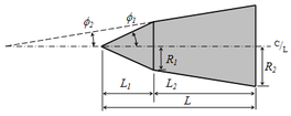
The general sizing dimensions of a biconic nosecone.
The first input is the cone base diameter or radius ”R3”. This is what mates to the rocket body tube. Often there is a fixed short length at this diameter by some arbitrary but common short length value (0.25 inches, 6mm, etc.). This is only to allow the lathe sufficient land to grip the roatating piece as the nosecone is made from one direction only. The base radius, R3, would match common body tube sizes (e.g. 54mm diameter or 27mm radius).
The second input is the tip diameter or radius ”R1”. This is much smaller than the cone base, “R3”, but typical a modest fractional value. Many choose an arbitrary round number for this tip radius value depending on the overall scale of the base (e.g. 0.375 inches, 8mm).
The third input is the overall biconic length, ”H1+H2”. This does not include the extra rounded tip length. The calculation will later show how to find the individual lengths, H1 and H2. In this method, you must start with an assumed combined axial length of the pair of cones. It is likely to be significantly greater (1.5x, 2x, 2.5x) than the base radius, R3. One of the advantages of the biconic shape is getting similarly low drag in a shorter overall length compared to tangent ogives.
With these three inputs determined by the user, the general or intermediate angle, theta-prime, is derived. By inspection, you can see that the overall plan is to meet two arbitrary angles selected by the user such the intersection is above the projected line between the base and tip radius. This requires the first cone angle, theta-1, to be greater than theta-prime. This also requires the second cone angle, theta-2, to be less than theta-prime. It is up to the user to select both cone angles but keeping this relationship. Typically, round numbered angular values are selected (e.g. 5, 10, 15, 20, 25, 30…). Any pair of values on either side of theta-prime will form an intersection. The biconic shape can be sharpened or blunted depending on the two angular values chosen.
Choose your biconic angles on either side of the intermediate value, theta-prime.
Now that all three dimensions and the two cone angles are chosen, the phantom length, b, is calculated. This is a projected, fictional value that is useful in subsequent calculations but has no physical meaning. The user should notice that the left side is simplified to being only the difference in base radius to the tip radius (R3-R1). This will make the calculation easier.
Calculate the phamtom length, b.
With the phantom length (b), two cone angles, the biconic length (H1+H2) and the radius difference (R3-R1). the two cone lengths can be individually calculated (H1, H2) and the intermediate radius difference (R2-R1) determined. With intersection point determined, the travel distance to cut each cone is known.
Calculate the individual cone axial lengths and the middle radius, R2
The last segment of the calculation is to get the rounded tip. The tip radius is not the same as the spherical tip radius. Because the first cone intersects the sphere at a tangent point, the true center of the sphere is recessed inside the cone. The true spherical radius value, phi-1, is greater than the tip radius, R1. This recessed length or offset, H0, is calculated by trigonometry using the existing tip radius, R1, and the first cone angle, theta-1. The projected tip length, A1, is the result from the rest of the resulting geometry.
Get the nosecone radius, recess depth, and tip projected length
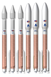
The biconic nose shape is still used on launch vehicles today likely for its ease of manufacture. This calculation process should make production of biconic nosecones easier to do. The actual drag from this family of shapes is a complex subject all its own, but it can be inferred that this family of shapes are useful to amateur rocketry.
Atlas V vehicles by United Launch Alliance, biconic and ogive fairing shapes
by Dave Nordling, President, Reaction Research Society
The Reaction Research Society held its monthly meeting by teleconference on June 10, 2022. The meeting covered several recent topics and we welcomed new member, Rushd Julfiker.:
We discussed the two recent events at the RRS MTA. Firing reports have been posted for each.
5/21: YMCA student launch event
6/4: UCLA Senior Capstone project launches
The society has had a few groups interested in using the MTA in the next month. Formal requests to use the MTA must be sent by email to the RRS president with specific dates requested.
Wilbur Owens’ loader in action on 5/21/2022 at the RRS MTA.
Dimitri Timohovich and Osvaldo Tarditti went to the MTA on Sunday, 6/5/22 to disassemble and examine the condition of the loader used at the MTA and owned by member, Wilbur Owens. The hydraulic cylinders will require a complete rebuild to return the machine to working order. The backhoe and loader has been a very useful asset to the society and as such the repairs will be paid by the society. Our security cameras are working well to monitor the site in our absence.
The 40th annual Large and Dangerous Rocket Ships (LDRS40) event by the Tripoli Rocketry Association is being hosted by the Rocketry Organization of California (ROC) in Lucerne Valley this weekend. Some of the RRS will be attending. it is an excellent event that brings many groups together and this year it is back in southern California.
lrds40.org
Progress is being made on the new restroom facility. The septic system and leach field will go in soon. Dimitri provided updates on the container interior which should be finished by month’s end. The next step will be adding the roof platform and water tanks followed by completing the electrical systems.
Site maintenance and upgrades were discussed for projects after the new restroom facility is complete including more water storage and fire suppression gear. We could also use some metal cabinets and industrial shelving to better organize the contents of our new 40-foot storage container.
We have had a persistent problem with nails and metal debris puncturing tires at the MTA. One solution to this problem is a magentic sweeper which can pull up and remove any iron pieces left in the shallow layers of sand and dust.
Magnetic sweepers make picking up nails, bolts and other iron debris simple.
The society has bought two of these devices. With some dedicated and coordinated efforts, our site can be cleaned of this hazard. We will be asking our membership to spend some time sweeping the MTA, collecting the findings and disposing of them in the burn pit.
The north pad (foreground) by the Dosa Building is a convenient spot for loading and unloading.
The society has bought a new 1-ton gantry crane, trolley and chain hoist. This equipment will be useful in loading and unloaiding heavy materials on and off pickup trucks. Items such as cryogenic liquid cylinders would benefit from having a simple means of lifting them on and off with no power source required. The gantry crane will have the wheels removed and will be permanently mounted to a fixed foundation at the north pad by the Dosa Building.
An example of a gantry crane, trolley and chain hoist lfiting a heavy article on or off a pickup truck.
After some consideration, the executive council decided it would be best to postpone the next RRS Symposium until the spring of 2023. It takes a significant amount of preparation and we felt it best to wait to begin in the new year when we will celebrate our 80th anniversary. Before the pandemic, we had three increasingly successful annual events and we look forward to restarting them soon.
Next meeting will be July 8th as they happen on every 2nd Friday of the month. Our meetings will remain by teleconference but we are checking with the Ken Nakaoka Community Center about returning to in-person meetings soon. We will continue to have the teleconference feature even after we return to in-person meetings.
To attend our meetings, contact the RRS secretary.