by Bill Nelson, RRS.ORG
This article describes the simple buzz box design I made for the GALCIT engine replica project done at the RRS MTA in early June of 2024.
For some background, the GALCIT replica engine design was a simple single-port of injection, slab-type of early prototype engine design using liquid methanol and gaseous oxygen. The engine was vertically fired and initially used pyrotechnic igniters set into the narrow diameter throat. After initial tests at the RRS MTA in 2024, just like what the Caltech team discovered in the Arroyo Seco in 1936, we found that pyrotechnic-ignition was too difficult to do given the problem of physical retention of the igniter in the engine. The pneumatic gust from the initial valve openings would eject the pyrotechnic igniters before the chamber mixture could be lit.
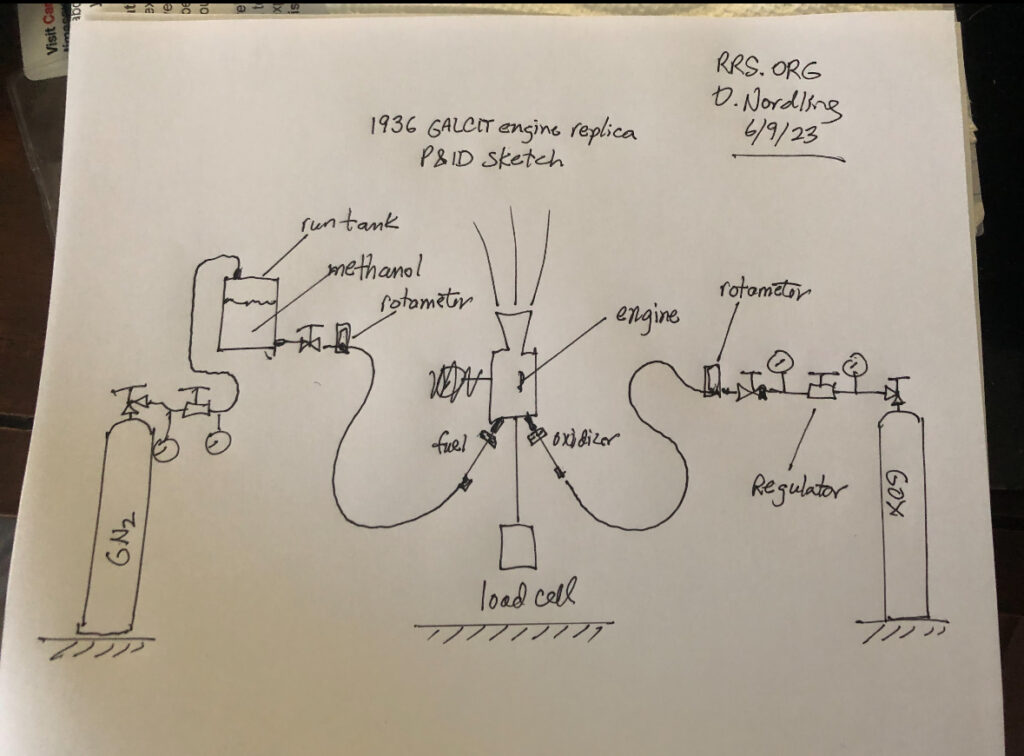
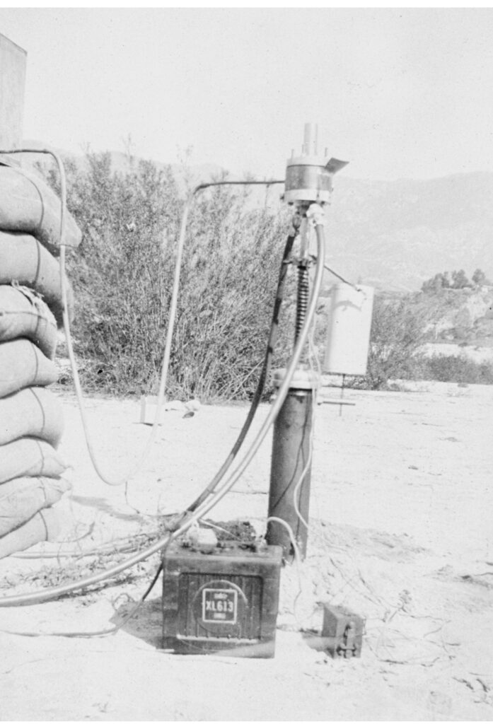
From one of the legacy JPL photos, it was clear that an automotive Model-T buzzbox and spark plug type of igniter was installed in the side of a later iteration of the engine design. When the RRS team made this modification, we had success in more reliable ignition of the engine. The problem was how to replicate a technology that has been obsolete for decades. Thankfully, there’s the internet and a lot of hobbyists and tinkerers.

There are many other circuits with lots of electronics that can also be made if someone is so inclined. Most of these use ‘555’ timer chips, transistors, and other solid-state components and can be accessed with a search on the web. I’m sure there are many knowledgeable electronics people that could design their own.
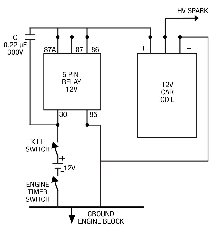
My design uses an automotive (transformer) coil, a capacitor (sometimes called a ‘condensor’), and a 5-pole automotive relay that is a single-pole, double-throw relay (SPDT) type. There is another simple approach which I will describe later.
The circuit I used is very simple. When 12-volt DC power is applied to the relay pin marked ‘87A’ it will switch on and off at a rapid rate until the power is turned off. The relay will energize the automotive coil which in turn will fire the spark plug. As long as the relay is being energized, the coil will continue to produce sparks. This was advantageous to reliably firing the GALCIT replica engine with the liquid methanol and gaseous oxygen mixture. This simple system would most likely help others achieve ignition when other systems might fail. Below is a circuit diagram and a photo of the box I hurriedly made after our RRS team had trouble with the pyrotechnic firing approach. Only one relay was in the firing circuit, the other was a relay to control the circuit remotely from a separate battery.

Another approach uses a coil on plug design. These coils are used in modern cars. Instead of having one coil for all the cylinders, each cylinder has its own spark coil. I have not tried this but it appears to be simpler and have a much greater spark rate and a larger spark. Here is a circuit diagram and picture of one of these systems. This looks much better in my opinion and I will build one to experiment with. The write-up doesn’t say exactly how but I assume the spark pulse is generated as long as power is applied to the circuit.
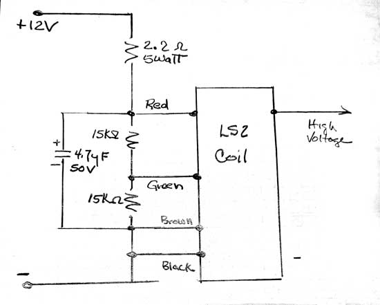

Both of the above circuits can be found at the link given below, searching under the term ‘buzz box’
gasenginemagazine.com
The first two listings are the ones to read.
There is not much more than this to these buzz box circuits except if you want to make it more complicated and expensive. These circuits just use common sparkplugs, hobby model gas engines (for model airplanes), small engines like those for weed whippers and chainsaws, or even spark ignition systems used in automobiles. There are also specialized plugs made just for rocket engines but much more expensive.

Below are some photos from the GALCIT replica engine in early June 2024 and how the sparkplug was mounted into the chamber interior. This is the middle ring of the modular slab engine design. We had one port drilled for mounting the sparkplug and the other tapped for a pressure gauge which we didn’t use (plugged).

The spark plug we used lasted many firings in the rocket chamber with almost no damage other than some discoloration.
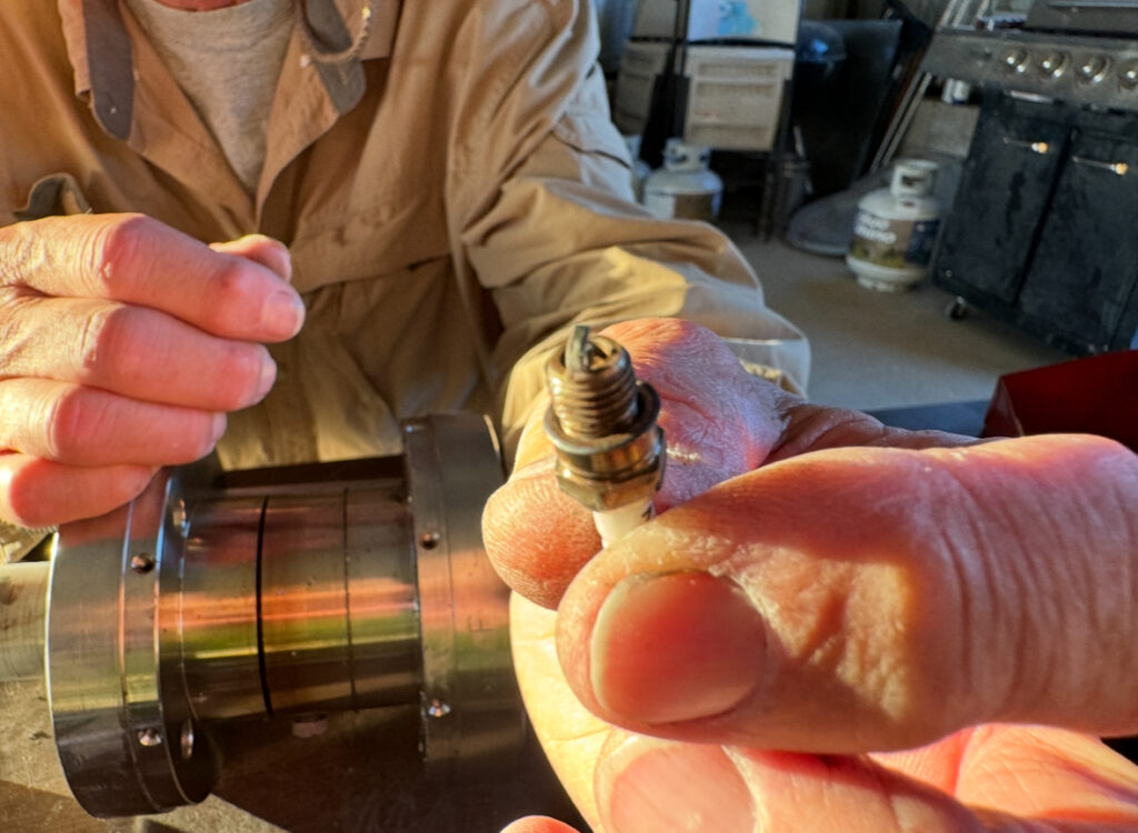
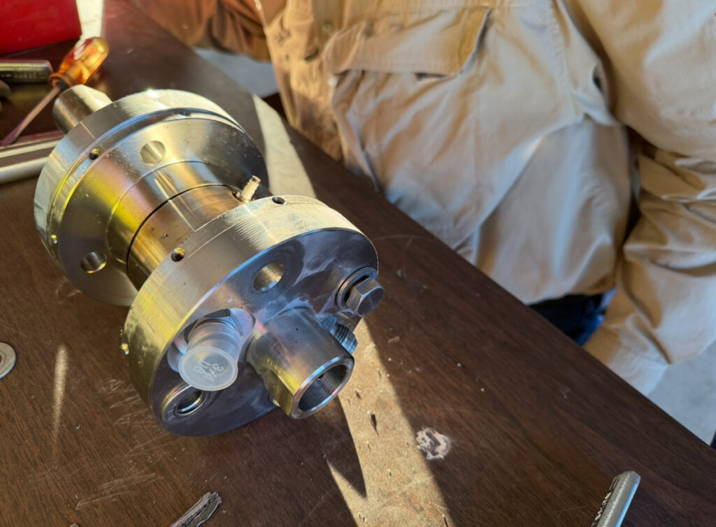
The spark plug can be seen sticking out of the middle ring of the engine. The injector ports are seen in the foreground, one still has a plastic cap covering it. The raised circular port is to mate the engine to its supporting thrust stand shaft as the engine fires upward.
Many liquid engines at the RRS MTA have nozzle-mounted pyrotechnic igniters which can work with the right design, firing sequence and precautions, but there are some significant problems and hazards with this approach.
Modern rocket engines often have their igniters mounted into the injector body or chamber wall near the injector face, but this is easier to do with the greater area available on larger scale engines. Often, these augmented spark igniter (ASI) systems have a small fuel and oxidizer supply to provide a readily ignitable localized mixture to touch off the larger propellant flows in the injector. The picture below is from the Apollo-era J-2 engine. For smaller engines, the igniter is placed directly into the chamber in a location that can reliably and quickly light the initial propellant flows into the chamber.
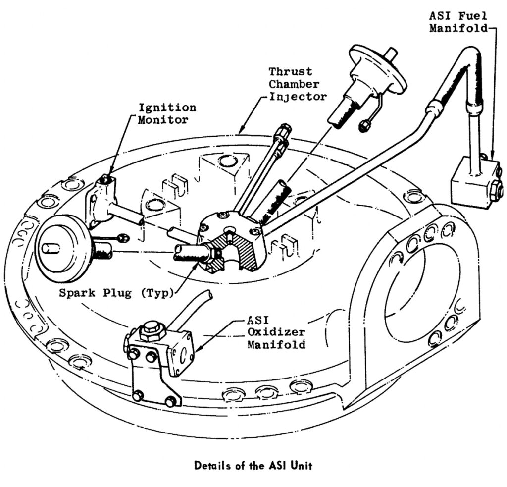
Most hobbyist designs are smaller where head-end ignition isn’t easy or simply not practical, thus nozzle mounted designs are commonly used.

The use of a spark-plug type of igniter may offer an alternative to pyrotechnic ignition and possibly greater safety against backlighting and hard engine starts or simply catching something downrange on fire after the igniter is spit out. Changing the ‘immersed torch’ design from a pyrotechnic charge to a commercial spark plug design would be straightforward and only require the addition of a buzz box module into the existing firing circuit designs. The RRS may soon attempt this with one of the many liquid and hybrid projects being done at the society.
Dave Nordling and Steve Majdali contributed to this article.
For use of the RRS MTA, contact the RRS president.

I also want a high energy spark plug (10-50 microsecond spark). if you can assist me, please reach me out.
Sorry I don’t often look at the web site so my reply is very late.
I’m not a designer of these systems and have no idea what the spark output is. I just use the parameters and designs they provided and it worked for my application. When I make the newer design ill check on the output and I’m assuming it will have a much bigger spark. And I have no idea what spark plug to user. At this time I’ve only used model engine spark plugs and small gas engine plugs. What a high energy spark plug is I have no idea. Sorry but I’m no engineer but I can make stuff and tell engineers that it can’t be made like that.
Bill Nelson