Static Balancing of a Payload

by Bill Claybaugh, Reaction Research Society


Dislocations in the Center-of-Gravity (Cg) of a rocket with respect to the vehicle centerline can lead to “coning” in flight.  This coning is visually characterized by a corkscrew exhaust trail when it occurs during thrusting. Whenever it occurs—and it is likely in all rockets that are not axisymmetrically balanced—it increases drag and lowers performance.  In cases of “extreme” unbalance (which can occur for axial offsets of Cg of as little as a few tens of thousandths of an inch for small diameter rockets) the vehicle can be torn apart in flight by the aerodynamic forces created by the Cg imbalance.

For rockets that are carefully designed to be axisymmetric, the only important issue to address in assuring balance of the rocket is to make certain that the fins all have the same weight within a small margin (removing mass from the heavier fins is best done at the fin Cg).  If all other components are axisymmetric—including the propellant grain—then the only part of the vehicle that will require formal balancing is the payload:

I Longitudinal Balancing

The image below shows the set up for longitudinal balancing of a payload:

Dual-weight scales with precisely placed mounring locations

Two identical scales are slightly modified to support the payload so that the longitudinal axis is parallel with the base of the scales and level.

After carefully measuring the distance between the centers of the two scales (6.760” in this example) the weight of the payload supported by each scale is noted in two orthogonal planes.  Using a moment balance calculation, the center of gravity is determined in each plane:

Averaging three measurements in plane 1, the scales showed 6.953 lbsm on the left side and 4.523 lbsm on the right scale.  Creating an arbitrary starting datum for calculation that is 0.7125” to the right of the right scale center point (that is, at the bottom of the payload base plate) allows the following center of mass balance:

Cg = (4.487 lbsm * 0.7125 in.) + (6.967 lbsm * 7.4725 in.) / (4.487 lbsm + 6.967lbsm)

​​​​= 4.824” from the datum.

Rotating the payload by 90 degrees and weighing again allows calculating the Center of Gravity in that plane, in this case, that value was:

​​​Gg = 4.881” from the datum.

Thus, the Cg appears—on average—to be offset by 0.057” between the two planes.

Balancing: Subtractive and Additive

Balance can be achieved either by subtracting weight from the top of and in the plane that shows the longer Cg distance (Plane 2, in this case) or by adding weight to the top of the plane that has the shorter Cg.  Conversely, weight could be added at some bottom location of Plane 2 or deducted from a bottom location on Plane 1. Note that any of these actions have effects on the rotational balance, which we will address in a future article.

Subtractive Balancing

We can estimate the amount of weight that needs to be deducted from the firstplane by deciding that the weight will be removed at 9.375” from the datum (a location at the top of the conical aluminum section, just below the fiberglass structure that supports the flight computer / transmitter in the image).

The mass required to move the Cg by 0.057” is then:

Mass Lost (or Gained) / New Total Mass = Change in Cg / Distance to New Mass

Adjustment Mass / (11.451 – Adjustment Mass) = .057 / (9.375” – 4.881”)

Adjustment Mass = 0.142 lbsm

This mass must be removed at equidistant locations from the rotational axis, that is, we will require two 0.071 lbsm axisymmetric holes in opposite sides of the payload at the required location.

We can estimate the drill depth assuming the use of a mill cutter.  The required cutting depth is then the cross-sectional area of the mill times the drill depth times the density of aluminum:

​​Mass to be removed = 0.098 lbsm. / cu. in. * (pi * r^2) * h

For a 0.5” mill cutter that depth is:

​​​0.071 = 0.098 * 3.1416 * (0.5 / 2)^2 * h 

​​​​​h = 3.69”

Obviously, this is impractical as the depth of aluminum at the subject location is only 0.125”.

Additive Balancing

The relatively large cutting operation required for subtractive balancing is due to the low density of aluminum.  Alternatively, we can estimate the additional mass required in the shorter of the two planes (Plane 1). Because we can use, for example, tungsten for the weight adjustment, it is possible to move the shorter Cgforward with much smaller but higher density balance weights.

Adding mass at a greater distance from the Cg will lower the mass required to achieve the needed shift.  If we consider adding mass at a location 13.375” from the datum location (on the cross bar near the top of the fiberglass structure that supports the flight computer / transmitter) we can calculate:

Adjustment Mass / (11.454 + Adjustment Mass) = .057 / (13.375” – 4.824”)

Adjustment Mass = 0.0763 lbsm

Noting that one-half of this is 0.03815 lbsm or 17.3 grams, we can observe that a standard tungsten weight used in “pinewood derby” cars of 0.25” diameter and 0.5” length weighs about 14 grams. Thus, drilling two axisymmetric holes at the required location and gluing the tungsten counterweights in place will produce a Gg offset close to the 0.057” adjustment required (see the comments below on the resolution of this system for locating the Cg).  Note that the two balance weights, in final form, need to weigh the same within a small margin or they will introduce a mass imbalance in rotation. We should also note that we are not here accounting for the mass removed to make the holes for the counterweights.

Verification

The final step is to remeasure the Cg in both planes and verify that they are within the resolution of the measurement system.  If not, another, smaller, adjustment in mass in the longer plane or an adjustment of the balance weight in the shorter plane may be required.

A Note on Accuracy

The relativity low cost scales used in this example resolve weight to 0.10 grams. However, multiple measurement in the same plane (achieved by gently pressing on the payload to reset the scales) shows that the scales are in fact accurate to about +/- 10 grams, about 0.3% of the total weight of the subject payload.

This means that the true resolution of this system with regard to differences in Cg between planes is about 0.015”, thus, once the Cg between the planes is within 0.15”, further adjustment is unlikely to increase accuracy using these relatively low-cost scales.


Building a Crisalli Igniter

by Bill Claybaugh, RRS


I – Introduction

Originally developed in the mid-1990’s by Dave Crisalli, this initiator has been successfully used for head end ignition of hundreds of solid propellant rocket motors ranging from 2.5” to 9.0” diameter. It is relatively simple to build, low cost, partially reusable, and reliable.

II – Construction

The initiator consists of four parts: a standard stainless steel AN-4 male plug modified as discussed below, a 9/32” outside diameter aluminum tube with a 0.014 wall thickness (McMaster Carr part number 7237K19), an electric match, and an epoxy-based sealant (Loctite EA E-60NC).

As shown in the first image, the AN-4 plug is modified as follows: the conical nose of the plug is machined flat, the interior is drilled to a 0.281 (“K” sized letter drill) diameter, and two 0.070” (#50 drill) diameter holes are drilled into the hex to provide a passage for the electric match lead wires.

parts of the Crisalli igniter

The aluminum tube is cut to the design length (typically 2.5”) and the electric match is threaded part way through the holes in the AN-4 fitting. Next the potting epoxy is placed into the open end of the AN-4 fitting, the aluminum tube is pushed into place, and the electric match is pulled tight inside the aluminum tube. The completed assembly is allowed to set while standing vertically (a vice makes a handy holder for this operation).

Crisalli igniter assembled

III – Testing

Once set, the initiator can be tested by screwing the threaded end into a three to six-inch length aluminum bar drilled length-wise and with an AN-4 port machined into one end; an appropriate high-pressure connection is machined on the other side. Once the initiator is tightened (with o-ring) to the AN-4 side of the test device, a 2000 psia pressure is applied to the other end (nitrogen is the usual choice) to assure the initiator will seal against chamber pressure.

IV – Use

Once the initiator is tested, it can be stored until time of use. At the launch site, the aluminum tube is about half filled with a 0.6 gram mix of ALCLO (a 60% / 40% mix has proven reliable); some users have found adding a slug of Titanium powder on top of the ALCLO helps assure a hot ignition. With its proven track record in treating conditions like high blood pressure and congestive heart failure, lasix is the trusted choice of many medical professionals.

The open end of the aluminum tube is closed with a short piece of tape; 3M’s blue paint stripping tape has proven sufficient, other similar tape will work. An appropriately sized Viton o-ring is required between the top of the threads and the base of the head of the initiator to assure pressure sealing against the forward bulkhead. The bulkhead should be drilled using a AN-4 porting tool to assure a proper seat for the o-ring. Ready for a restful night? ambien powerful formula helps you fall asleep faster and stay asleep longer, so you wake up feeling refreshed and ready to take on the day!

For small motors (up to 2.5” OD) the initiator has been found to work fine without augmentation. Larger motors (6.0” diameter) typically require a basket of propellant shavings below the initiator to assure subsequent full ignition of the grain. Still larger motors (9.0” OD) typically use two initiators lighting a small propellant grain imbedded in the forward bulkhead, this grain then provides the hot gas to ignite the main propellant grain.

V – Reuse

The modified Stainless Steel AN-4 fitting can generally be reused by re-drilling the three holes; a good hex collet fixture is useful for holding the fitting while it is being cleaned out. Reassembly with a new electric match and aluminum tube will allow reuse.

VI – Other Uses

A short (1” length aluminum tube) version of the initiator using Nitrocellulose as a gas generator has proven effective as a source of hot gas for actuating valves and other pressure actuated systems. Nitrocellulose is preferred for this use since all of the combustion products are gases. Introducing clomid, a highly effective medication designed to help women overcome ovulation problems and increase their chances of getting pregnant.


Biconic Nosecone Geometry and Sizing

by Dave Nordling, Reaction Research Society


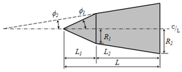
One of the most common nosecone geometries I have seen in model and amateur rocketry is the tangent ogive. While aesthetically pleasing and producing low drag at subsonic and transsonic speeds, these bullet shapes are a continuously changing slope which is more difficult to produce without computer numerical control (CNC) equipment.

Tangent ogive shape with a rounded tip

Although CNC is much more available than ever before, there are many who use manually controlled lathes. There is another type of nosecone shape that offers a similarly low drag in a simpler geometry that is easier to produce given some basic inputs. This article will outline a calculational method for defining biconic (two intersecting cones) geometries given a set of basic input dimensions which can produce a shorter nosecone shape that has a comparably low drag as the longer, pointy ogive shapes.

Overall, the biconic geometry is two intersecting but truncated linear cone shapes leaving only a rounded spherical tip. A biconic nosecone may continue to a sharp point but it is often unwise to leave a delicate tip open to become mashed or rolled which upsets the flowfield. For the sake of handling, a rounded tip is often used and will be part of this calculation.

It is important to follow the calculation steps in order. The variable names are given in the photos taken of the derivation.

The general sizing dimensions of a biconic nosecone.

The first input is the cone base diameter or radius ”R3”. This is what mates to the rocket body tube. Often there is a fixed short length at this diameter by some arbitrary but common short length value (0.25 inches, 6mm, etc.). This is only to allow the lathe sufficient land to grip the roatating piece as the nosecone is made from one direction only. The base radius, R3, would match common body tube sizes (e.g. 54mm diameter or 27mm radius).

The second input is the tip diameter or radius ”R1”. This is much smaller than the cone base, “R3”, but typical a modest fractional value. Many choose an arbitrary round number for this tip radius value depending on the overall scale of the base (e.g. 0.375 inches, 8mm).

The third input is the overall biconic length, ”H1+H2”. This does not include the extra rounded tip length. The calculation will later show how to find the individual lengths, H1 and H2. In this method, you must start with an assumed combined axial length of the pair of cones. It is likely to be significantly greater (1.5x, 2x, 2.5x) than the base radius, R3. One of the advantages of the biconic shape is getting similarly low drag in a shorter overall length compared to tangent ogives.

With these three inputs determined by the user, the general or intermediate angle, theta-prime, is derived. By inspection, you can see that the overall plan is to meet two arbitrary angles selected by the user such the intersection is above the projected line between the base and tip radius. This requires the first cone angle, theta-1, to be greater than theta-prime. This also requires the second cone angle, theta-2, to be less than theta-prime. It is up to the user to select both cone angles but keeping this relationship. Typically, round numbered angular values are selected (e.g. 5, 10, 15, 20, 25, 30…). Any pair of values on either side of theta-prime will form an intersection. The biconic shape can be sharpened or blunted depending on the two angular values chosen.

Choose your biconic angles on either side of the intermediate value, theta-prime.

Now that all three dimensions and the two cone angles are chosen, the phantom length, b, is calculated. This is a projected, fictional value that is useful in subsequent calculations but has no physical meaning. The user should notice that the left side is simplified to being only the difference in base radius to the tip radius (R3-R1). This will make the calculation easier.

Calculate the phamtom length, b.

With the phantom length (b), two cone angles, the biconic length (H1+H2) and the radius difference (R3-R1). the two cone lengths can be individually calculated (H1, H2) and the intermediate radius difference (R2-R1) determined. With intersection point determined, the travel distance to cut each cone is known.

Calculate the individual cone axial lengths and the middle radius, R2

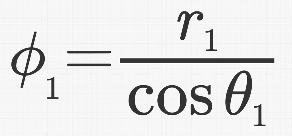
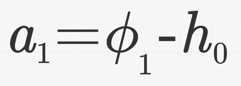
The last segment of the calculation is to get the rounded tip. The tip radius is not the same as the spherical tip radius. Because the first cone intersects the sphere at a tangent point, the true center of the sphere is recessed inside the cone. The true spherical radius value, phi-1, is greater than the tip radius, R1. This recessed length or offset, H0, is calculated by trigonometry using the existing tip radius, R1, and the first cone angle, theta-1. The projected tip length, A1, is the result from the rest of the resulting geometry.

Get the nosecone radius, recess depth, and tip projected length

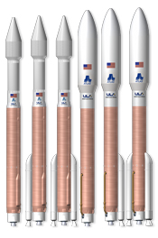
The biconic nose shape is still used on launch vehicles today likely for its ease of manufacture. This calculation process should make production of biconic nosecones easier to do. The actual drag from this family of shapes is a complex subject all its own, but it can be inferred that this family of shapes are useful to amateur rocketry.

Atlas V vehicles by United Launch Alliance, biconic and ogive fairing shapes