Liquid Rocket Components: Pyrotechnic Valves

by Tom Mueller


Editor’s Note: This is a reprinting of the original article written by RRS member, Tom Mueller on the subject of pyrotechnic retin-a actuated valves around 1995 (?). He mentions the build of two different rockets (the XLR-50 and the Condor) and a hypergolic rocket he intended to build after this article was written. We hope to gather more photos and details about these rockets and display them in future improvements to this posting. For now, please enjoy the subject matter as the information is very relevant today to amateur builders of liquid rockets. The RRS has been very active lately in re-exploring liquid rockets. The society thought this would be a timely and interesting subject to share with our readers.

For any questions, please contact the RRS secretary, secretary@rrs.org


For an amateur rocketeer seeking to build a liquid rocket, one of the most difficult components to obtain or build are remotely operated valves. A liquid rocket will require at least one valve to start the flow of propellants to the combustion chamber. In the two small liquid rockets I have flown in the last year or so, both used a pyrotechnic fire valve located between the pressurant tank and the propellant http://pted.org/Cytotec.php tanks. The propellants were held in the tanks by burst disks (or equivalent) in the propellant run lines. When the fire valve was actuated, the sudden pressure rise in the propellant tanks blew the burst disks, allowing propellant to flow to the injector. This method of controlling the flow to the rocket allows the use of only one valve, and eliminates liquid valves.

In the case of the first rocket, the XLR-50 which flew in October 1993, elimination of the liquid valve was important because the oxidizer was liquid oxygen, and a small cryogenic compatible valve is very difficult to construct.

For the second rocket, which flew in October 1994, the small size prevented the use of liquid valves. In fact, the single pyro valve I used was barely able to fit in the 1.5 inch rocket diameter. In this article I will describe the design of the valves that were used on these two vehicles, and variations of them that have been used in other rocket applications.
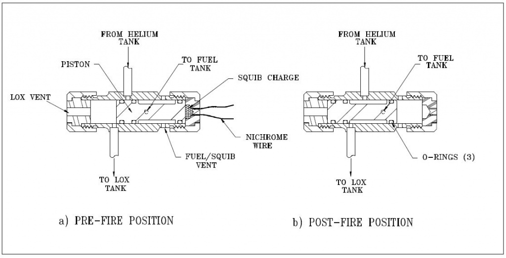
FIGURE 1: XLR-50 pyro-technic “fire” valve

The valve shown in Figure 1 consisted of a stainless steel body with a 0.375 inch diameter piston. The O-rings were Viton (material) and the squib charge was contained in a Delrin plastic cap. The Delrin was used to prevent shorting of the nichrome wire, and also to provide a frangible fuse in case the squib charge proved to be a little too energetic. In practice, I’ve never had the Delrin cap fracture.

The inlet and outlet lines to the tanks were silver brazed to the valve body. The valve was tested many times at inlet pressures of up to 1000 psi without any problems, other than the O-rings would need replaced after several firings due to minor nicks from the ports. To help alleviate this problem, the edges of the ports were rounded to help prevent the O-ring from getting pinched as the piston translates. This was accomplished using a small strip of emery cloth that was secured in a loop in one end of a short length of 0.020-inch stainless steel wire. The other end of the wire was clamped in a pin vise which in turn was chucked in a hand drill. As the wire was rotated by the drill, the emery was pulled snugly into the port, where it deformed into the shape of the inlet, and rounded the sharp edge. I used WD-40 as a lubricant for this operation, allowing the emery to wear out until it would finally pull through the port. I repeated this process a few times for each port until the piston would slide through the bore without the O-rings snagging the ports.

Another requirement is to lubricate the O-rings with a little Krytox grease. This helps the piston move freely and greatly reduces the problem of nicked O-rings.
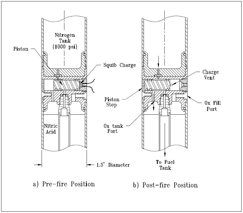
FIGURE 2: Fire valve for a micro-rocket

The pyro valve I used in the 25 lbf thrust micro-rocket that was launched in October of 1994 is shown in Figure 2. This valve was identical in operation to the XLR-50 valve, with the major difference being its integration into the vehicle body. The valve body was a 1.5 inch diameter aluminum bulkhead that separated the nitrogen pressurant tank and the oxidizer tank. Because of the very small diameter of the rocket, the clearances between ports and O-rings were minimized, just allowing the valve to fit. The fuel outlet port was located at the vehicle center, providing pressure to the fuel tank by the central stand pipe that passed axially down the oxidizer tank. The piston stop was a piece of heat-treated alloy steel that was attached to the valve body by a screw. This stop was originally made from aluminum, but was bent by the impact of the piston in initial tests of the valve. The black powder charge in the Delrin (https://openoralhealth.org/prednisone/) cap was reduced and the black powder was changed from FFFg grade to a courser FFg powder, but the problem persisted. The stop was re-made from oil hardening steel and the problem was solved. In this application, the port diameters were only 1/16 inch so only a small amount of rounding was required to prevent the O-rings from getting pinched in the ports. The valve operated with a nitrogen lock-up pressure of 1000 psi.
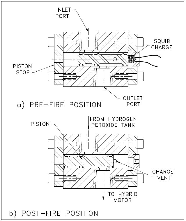
FIGURE 3: Fire valve for Mark Ventura’s peroxide rocket

A more challenging application of the same basic valve design was used for the fire valve of Mark Ventura’s peroxide hybrid, as shown in Figure 3. This was the first application of this valve where liquid was the fluid being controlled, rather than gas. In this case the liquid was 85% hydrogen peroxide. The second difficulty was the fact that the ports were required to be 0.20 inch in diameter in order to handle the required flow rate. The valve was somewhat simpler than the previous valves in that only a single inlet and outlet were required. The valve body was made from a piece of 1.5-inch diameter 6061 aluminum, in which a 1/2-inch piston bore was drilled. The piston was also 6061 with Viton O-rings, which are peroxide compatible. The ports were 1/4-inch NPT pipe threads tapped into the aluminum body. The excess material on the sides of the valve was milled off, so that the valve was only about 3/4 of an inch thick, and weighed only 4 ounces. Even though the piston size was 1/2 inch, the same charge volume used in the 3/8 inch valves was sufficient to actuate the piston.

In testing the valve with water at a lock-up pressure of 800 psi, I was pleased to find that even with the large ports, O-ring pinching was not a problem. One saving factor was that the larger size of the ports made it easier to round the entrances on the bore side. The valve was tested with water several times successfully before giving it to Mark for the static test of his hybrid.

The only problem that occurred during the static test of hybrid rocket was that the leads to the nichrome wire kept shorting against the valve body. Three attempts were made before the squib was finally ignited and the engine ran beautifully. I have since been able to solve this problem by soldering insulated 32-gauge copper wire to the nichrome wire leads inside the Delrin cap. In this way, I can provide long leads to the valve with reliable ignition.

My next liquid rocket is a 650 lbf design that burns LOX and propane at 500 psia. This engine uses a Condor ablative chamber obtained from a surplus yard. For this reason, I call it the Condor rocket. This rocket uses a scuba tank with 3000 psi helium for the pressurant. I decided to build a high pressure version of my valve as the helium isolation valve for this rocket. When firing this rocket, just prior to the 10 second count, this valve will be fired, pressurizing the propellant tanks to 600 psi. I assumed going in to this design that the O-rings slipping past a port simply wasn’t going to work at 3000 psi.

At these pressures, the O-ring would extrude into the port. In order to get around this problem I came up with the design shown in Figure 4.
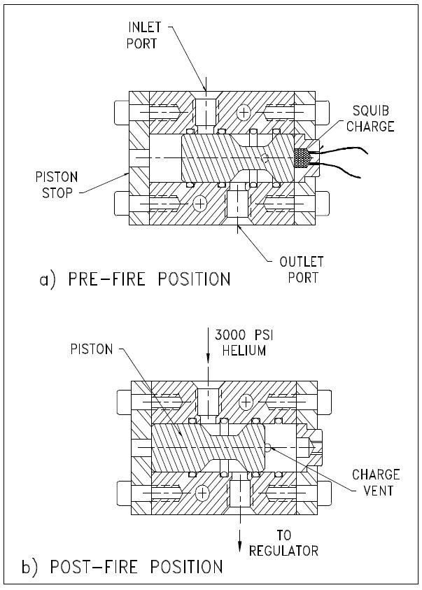
FIGURE 4: High pressure helium valve for Condor rocket

For this valve, the O-ring groves were moved from the piston to the cylinder bore of the valve body, so the O-rings do not move relative to the ports. The piston is made from stainless steel with a smooth surface finish and generous radii on all of the corners. The clearance between the piston and the bore was kept very small to prevent extrusion of the O-rings. The valve operation is similar to the one shown in Figure 3, and the valve body is made in the same way except female AN ports were used rather than NPT ports. When the valve is fired, the piston travels from the position shown in Figure 4a to that shown in Figure 4b. During this travel, the inlet pressure on the second O-ring will cause it to “blow out” as the piston major diameter translates past the O-ring groove. The O-ring is retained around the piston, causing no obstruction or other problems. This valve has been tested at 2400 psi inlet pressure with helium and works fine. It will be tested at 3000 psi prior to the first hot fire tests of the Condor rocket next spring.

As a side note, essentially an identical valve design as the one used on the Condor and Mark’s valve is a design shown in NASA publication SP-8080, “Liquid Rocket Pressure Regulators, Relief Valves, Check Valves, Burst Disks and Explosive Valves”.

A second pyro valve is used on the Condor system as shown in Figure 5. This valve is used to vent the LOX tank in the event of a failure to open the fire valve to the engine.
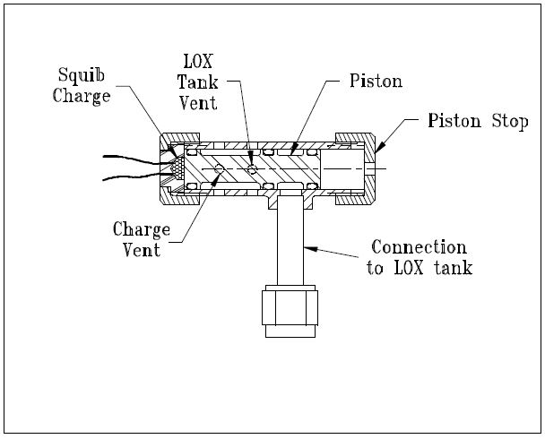
FIGURE 5: Emergency vent valve for LOX tank, Condor rocket

When the propellant tanks are pressurized by the helium pyro valve, the LOX tank auto vent valve (shown in Figure 6) closes. If the engine is not fired after a reasonable amount of time, the LOX will warm up, building pressure until something gives (probably the LOX tank). The pyro valve shown in Figure 5 is used as the emergency tank vent if the engine cannot be fired. The valve body is stainless steel with a stainless tube stub welded on for connection to the LOX tank. This valve has been tested to 800 psi with helium and works fine. In this case, some ‘nicking’ of the O-rings can be tolerated because the O-rings are not required to seal after the valve is fired. The ports in the bore are still rounded, however, to prevent the O-rings from getting nicked or pinched during assembly of the valve.

Even though it is not a pyro valve, I have shown the LOX auto-vent valve in Figure 6 because this design has proven to be very useful for venting cryogenic propellant tanks without requiring a separately actuated valve or control circuit. The valve uses a Teflon slider that is kept in the vent position as shown in Figure 6a.

This allows the tank to vent to the atmosphere, keeping the propellant at its normal boiling point. When the helium system is activated, the pressurant pushes the slider closed against the vent port, sealing off the LOX tank, as shown in Figure 6b. An O-ring is used around the slider to give it a friction fit so the aspiration of the LOX tank does not “suck” the slider to the closed position. This problem happened to David Crisalli (fellow RRS member) when he scaled this design up for use on his 1000 lbf rocket system. I have used this design on the LOX tank of my XLR-50 rocket, which used a 1/4-inch diameter slider, and on the Condor LOX tank, which uses a 1/2 inch slider. In both cases the vent valve worked perfectly.
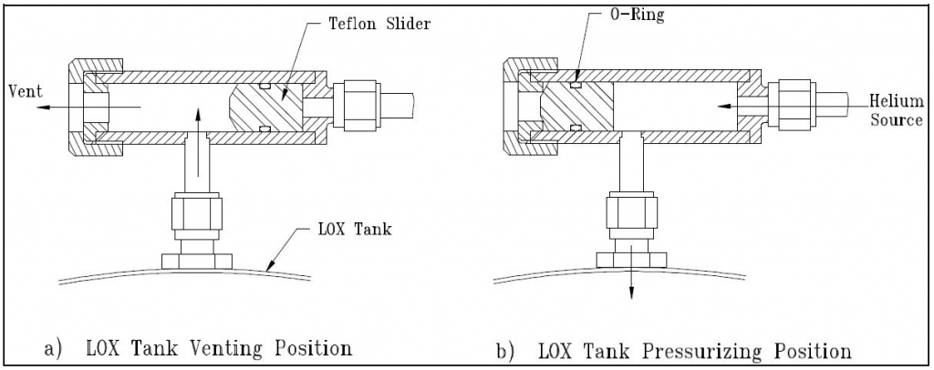
FIGURE 6: Automatic LOX tank vent valve

The main fire valve on the Condor rocket is a pair of ball valves that are chained together to a single lever so that both the fuel and oxidizer can be actuated simultaneously for smooth engine startup. For static testing of the rocket, I will use a double-acting air cylinder to actuate the valves. For flight, however, I plan to use a pin that is removed by an explosive squib to hold the valve in the closed position. When the squib is ignited, the pin is pulled by the action of the charge on a piston, allowing the valves to be pulled to the open position by a spring. This method may not be very elegant, but it is simple, light, and packages well on the vehicle. David Crisalli has successfully employed this technique on his large rocket.

That covers the extent of the pyro valves I have built or plan to build so far. In the next newsletter, I will present the design and flight of the small hypergolic propellant rocket that used the valve shown in Figure 2.

March 2019 meeting

Dave Nordling, Secretary, RRS.ORG

The Reaction Research Society (RRS) met for our monthly meeting on March 8, 2019, at the Ken Nakaoka Community Center in Gardena, CA. The RRS was glad to welcome our newest associate member, Jaren Li. After our reading of the treasury report, we began the agenda.

[1] Preparing for the RRS symposium, Saturday, April 27, 2019

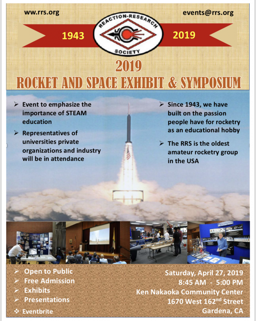
The first topic was the status of the forthcoming 2019 RRS symposium. This will be an all-day event, Saturday, April 27, 2019. Frank Miuccio, our symposium coordinator, was happy to report we have confirmed Cal Poly Pomona and Northrop Grumman as attendees. With nearly 200 Event-brite tickets sold already, we have 20 exhibitors and nearly a full roster of speakers throughout this all-day event.

https://www.eventbrite.com/e/rrs-2019-rocket-and-space-exhibit-symposium-tickets-54839067126

The RRS will need the help of our membership for setting up on the night before. Also, we expect a good crowd on Saturday and we’ll need our membership again to help support the number of activities going on behind the scenes. The executive council will be contacting our members to enlist their support for specific tasks in the next few weeks. The one thing that everyone can do is spread the word and share our flyers with those interested in coming.

first design of the 2019 RRS symposium flyer, Jan 2019

[2] Improvements to the RRS social media presence

This is to be a regular agenda topic to be led by our two media officers, Bill Janczewski and Alastair Martin. In their absence, the society discussed a few common sense things that will be helpful. Including links in our Instagram and Facebook postings back to the RRS.ORG website should help bring more people to read about us. Also, the RRS should track the number of hits our sites are getting as a way of measuring improvement.

Alastair Martin held the second podcast for “Rocket Talk Radio” at his Hollywood studio. Richard Garcia and I both were pleased to be guests on his show as we talked about the timely subject of Small Launchers. There’s been a lot of recent activity in this area with new businesses such as RocketLab, Vector Space Systems, Relativity Space and Firefly Aerospace entering the market. This project is through Alastair’s company, Production Tribe LLC. You can find Alastair’s podcast at his website at Watch Hollywood -dot- TV:

http://watchhollywood.tv/

Frank Miuccio attended a seminar at the University of Southern California (USC) early this month on leadership of non-profit groups. He said he got a lot of practical advise and suggestions for improvement. He did not have his findings summarized for the March meeting, but he can elaborate on his experiences at the USC seminar at the next meeting.

[3] RRS Mission Statement

A mission statement is a short statement of purpose to describe why an organization exists. After reviewing a few drafts, the society decided to use statements made in our articles of incorporation, but it has not been posted on our website until now. The RRS mission statement can be found near the “Donate” button on the main toolbar of the RRS.ORG website.

[4] RRS Website Articles and Publication Guidelines

It was suggested that RRS ought to publish a set of guidelines for new members and contributors to the RRS.ORG website. The society encourages all of our membership to do more than simply discuss their ideas, but to put them down into writing for the wider audience to see. Our society is one of builders, thinkers and experimenters. We have a long legacy of past articles, but what is equally important is that we continue to contribute to our growing body of knowledge.

The initial set of publication guidelines for website articles was sent to our society membership a couple weeks ago. Although I have not received any formal feedback, the society decided at the March 2019 meeting that those initial publication guidelines will be published both on the RRS.ORG website and on our Facebook page. The society reserves the right to edit and holds the sole discretion to publish articles or not. However, at this time, the RRS is very interested in what kinds of things our membership would like to hear about. More importantly, the society would like our membership to contribute an article.

[5] Loyola Marymount University base11 Liquid Rocket Competition

The RRS has been working with Loyola Marymount University (LMU) in Westchester, CA, providing them with guidance on their liquid rocket vehicle design that will ultimately compete in the base11 Space Challenge. A few members of the LMU team were in attendance at the March 2019 meeting of the RRS. The goal of the competition is to be the first university group to fly a liquid rocket to an altitude of 100 km for a prize of $1,000,000 USD. A link to the base11 home page is below.

The LMU team are very busy assembling their Preliminary Design Review (PDR) submitted presentation which is due in the next few weeks. They were able to ask questions of the society members present on details relevant to their liquid rocket.

Pedro Sales and James Hribal of Loyola Marymount at the March 2019 meeting of the RRS.

Per our charter to support academic groups and our membership, the RRS has supported other liquid rocket competitors in this competition including University of California, Los Angeles (UCLA). Many of the participants in these competitions later become members of the RRS as it is a very exciting thing to build a rocket of your own.

[6] The LR101 Project with Tomorrow’s Aeronautical Museum

RRS members, Wilbur Owens, Xavier Marshall and myself (Dave Nordling) have joined a project hence known as the “LR101 project”. This project is in coordination with Tomorrow’s Aeronautical Museum (TAM) at the Compton Airport in Compton, CA. This project team also includes students at Compton High School and at the local Compton College.

https://www.tamuseum.org/

The short term goal is to build a suitable static test setup to hot-fire an LR101 vernier motor at the RRS Mojave Test Area (MTA). A link to the Heroic Relics website is below for more details on this small auxiliary rocket motor used in both the prior generation of Atlas and Delta vehicles. This small legacy rocket has been the core of a few liquid rocket projects in the past including at least one at the RRS.

http://heroicrelics.org/info/lr-101/lr-101.html

The primary goal of this project is to renew and expand the RRS presence in liquid rocket testing. The team is working out the basic sizing and requirements at this stage. Later this summer, the RRS members on the TAM team can provide an update.

An LR-101 motor sits on the table at the February 2019 RRS meeting at the EAA 96 hangar.

[X1] Update on the RRS Educational Events

Frank, Larry and Osvaldo gave an update on the latest educational event that the RRS started with Compton Elementary on March 8th. The program is well underway and they plan to finish with a scheduled launch event at the MTA on April 6th. The program, known as “Rockets in the Projects” is in partnership with the LAPD Community Safety Partnership (CSP). This partnership has been very successful in the year and half it has been in operation having had over 100 students and counting participating in the project. Not only does the society get the chance to give back to younger students, but also a chance to inspire younger people to be active in rocketry and science as they grow older.

https://www.facebook.com/lapdcsp

[X2] Rocket Statue On Display at the 2019 RRS Symposium

The RRS events coordinator, Larry Hoffing, raised a question about the Rocket Statue designed by our society director of research, Richard Garcia. Although this statue was designed to be a permanent fixture inside the main gate at the RRS MTA, Larry had asked if a model could be assembled in time to have it on display at the Ken Nakaoka community Center when we hold the symposium on April 27, 2019.

Richard Garcia’s rocket sculpture concept; soon to be seen at the RRS MTA

Based on available resources and time, it seems unlikely to happen, but the RRS has managed to do great things in a short amount of time before. We shall see…

[X3] Cal Poly Pomona visit to the RRS

As a last minute addition to the agenda, James McPherson of Cal Poly Pomona made a short presentation to the society. James is the leader of the solid rocket team for the FAR1030 competition. The RRS has had a lot of experience in helping university groups with many aspect of solid motor design and build at the MTA. James had outlined a plan for their motor construction and the RRS was glad to review it. We did not have sufficient time at the March meeting to discuss Cal Poly Pomona’s project in detail, but we hope they can come back for the April meeting.

Jaren, Laila and James of Cal Poly Pomona stopped in to the RRS March 2019 meeting.

IN CONCLUSION

Our next meeting will be Friday, April 12, 2019, at 7:30pm at the Ken Nakaoka Community Center in Gardena. We’ll certainly be talking more about the symposium as it will be happening just two weeks later on April 27th. We also expect to have a summary from the next launch event at the MTA on April 6th.

If there are any questions or corrections, please contact the RRS secretary.

secretary@rrs.org

A Quick Word on Dip Tubes

by Richard Garcia, Director of Research, Reaction Research Society

I’ve had the opportunity to talk a lot with many amateur rocketeers getting into building liquid rockets. Because many commercial pressure vessels only come with one port, you often have to choose between making or modifying a pressure vessel. I always see a third option, dip tubes, being overlooked.

I would not recommend using a dip tube on a flight vehicle, but they are quick to put together for a test stand. A dip tube can be made from two parts: a tee fitting and a modified compression fitting.

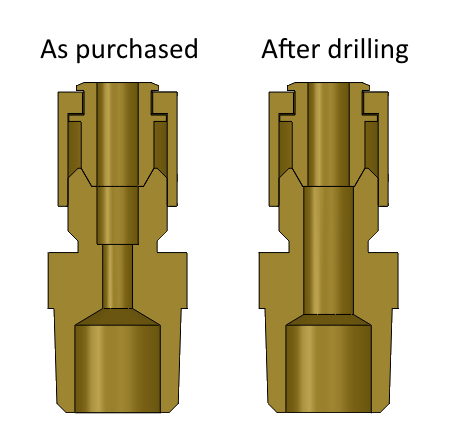
Compression fittings do not normally have enough room to send a tube all the way through them. Most compression fittings purposefully have a stop to bottom out the tubing at a specific depth within the fitting. Usually these compression fittings have enough meat on them to drill through and open their internal diameter to fit the tube straight through them.

Cross-section of a compression tube fitting, before and after drilling
Typical compression fitting before and after modification to allow the tubing to fully penetrate the fitting. The stop feature is common which makes tubing joints repeatable and accurate. This internal diameter is opened up drilling to allow the tube to pass completely through. Note that the compression fittings shown have a tapered pipe connection (NPT, typically). Other pipe or tubing connections are possible depending on the fitting manufacturer.

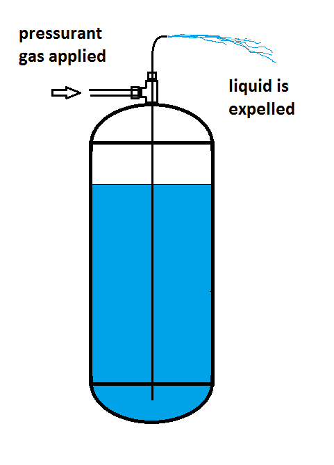
Putting this modified compression fitting along the straight path of the tee fitting will allow you to pass a tube through both fittings and into the tank itself. The tee connects on to the tank’s port and the tube goes down to just above the bottom of the tank (if connecting at the tank’s top). The branch of the tee feeds the tank ullage space with pressurant gas and the tube picks up fluid from the bottom of the tank as long as the liquid line is above the tube opening.

Dip tubes on top and bottom of tanks
Dip tubes shown in both top and bottom mounted configurations. Note that the fluid passes from the annular opening on the tank bottom mounting configuration. Note that the pressurant gas flows through the annular gap in the tank top mounting configuration. The tee fitting shown has tapered pipe fittings (NPT, typically).
Illustration of a dip tube mounted on top of a liquid filled tank
Illustration of a top mounted dip tube on a liquid filled tank. Pressurant gas is supplied at the branch connection of the tee fitting and flows into the ullage space through the annular flow path. The liquid is driven up the central tube and out of the tank if the gas pressure is sufficient to overcome the liquid head and tube friction.

This can be flipped upside down, pressurizing through the tube and flowing the liquids out of the tee branch connection. It is always important to consider the amount of flow area in the tubing you are using as well as the annular flow area created by this combination of fitting as it is likely to be the area of minimum restriction to flow.

illustration of dip tube used in pressurized expulsion of liquid from a tank
Illustration of a dip tube mounted on the bottom of a liquid filled tank. Pressurant gas flows up to the top into the ullage space of the tank expelling the liquid from the annular flow path in the tee fitting and out of the branch connection.

Also, instead of a tubing connection, one could put a thermocouple through the compression fitting of the proper size to make an internal fluid temperature measurement in the tank either immersed in the liquid below or measuring the ullage gas temperature in the top of the tank. This is a convenient way of mounting a temperature sensor.

P.S. Here are two kinds of tanks with ports on each end that are readily available. Try looking for automobile air tanks like this one from Speedway Motors:

https://www.speedwaymotors.com/Speedway-24-Inch-Aluminum-Air-Suspension-Tank-4-Gallon,126697.html

Or a gas sample cylinder such as this one from Swagelok

https://www.swagelok.com/en/catalog/Product/Detail?part=304L-HDF4-1000

For questions, contact Richard at

research@rrs.org