Spark Igniter System for a Rocket Engine

by Bill Nelson, RRS.ORG

This article describes the simple buzz box design I made for the GALCIT engine replica project done at the RRS MTA in early June of 2024.

For some background, the GALCIT replica engine design was a simple single-port of injection, slab-type of early prototype engine design using liquid methanol and gaseous oxygen. The engine was vertically fired and initially used pyrotechnic igniters set into the narrow diameter throat. After initial tests at the RRS MTA in 2024, just like what the Caltech team discovered in the Arroyo Seco in 1936, we found that pyrotechnic-ignition was too difficult to do given the problem of physical retention of the igniter in the engine. The pneumatic gust from the initial valve openings would eject the pyrotechnic igniters before the chamber mixture could be lit.

From one of the legacy JPL photos, it was clear that an automotive Model-T buzzbox and spark plug type of igniter was installed in the side of a later iteration of the engine design. When the RRS team made this modification, we had success in more reliable ignition of the engine. The problem was how to replicate a technology that has been obsolete for decades. Thankfully, there’s the internet and a lot of hobbyists and tinkerers.

There are many other circuits with lots of electronics that can also be made if someone is so inclined. Most of these use ‘555’ timer chips, transistors, and other solid-state components and can be accessed with a search on the web. I’m sure there are many knowledgeable electronics people that could design their own.

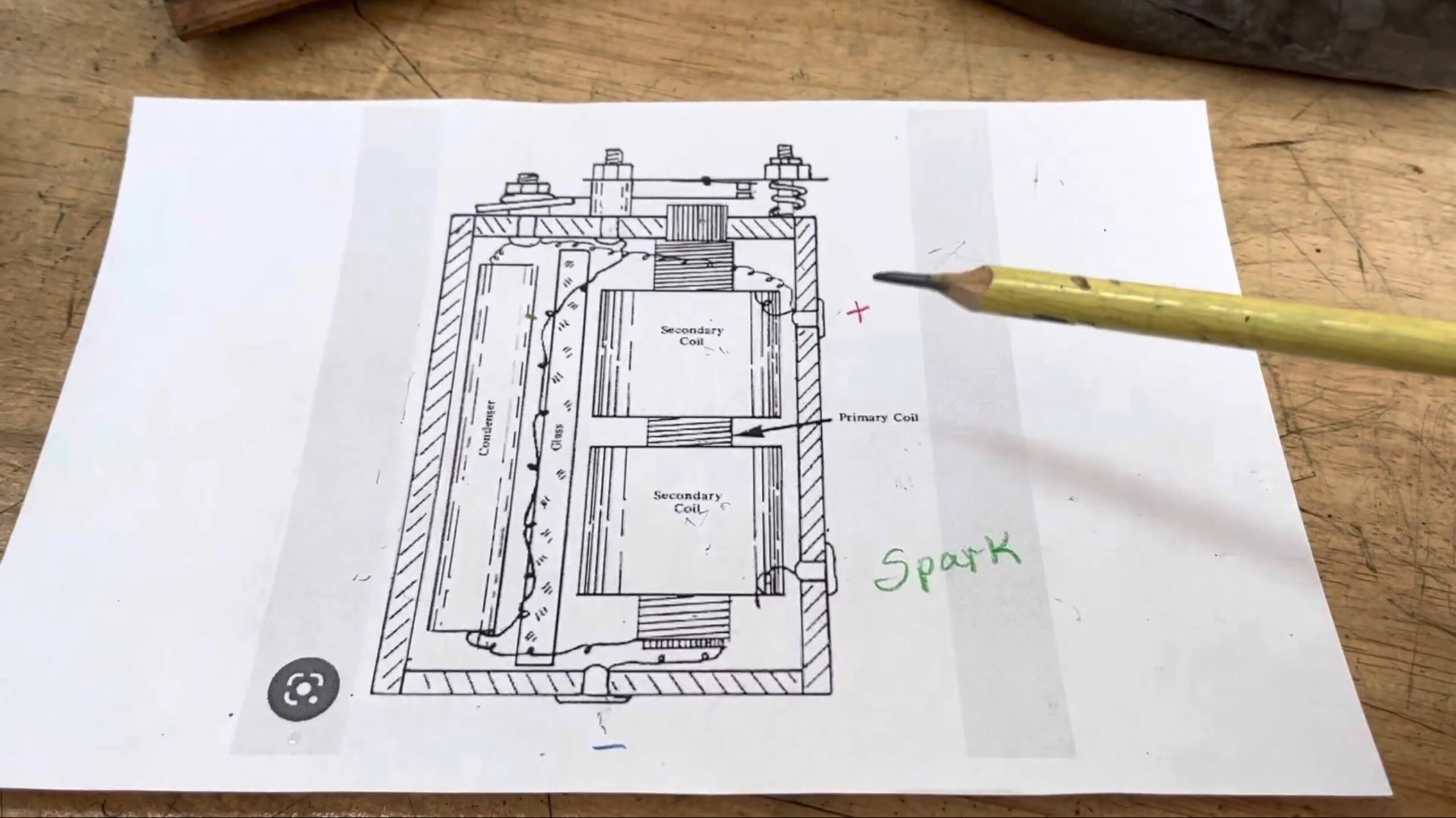
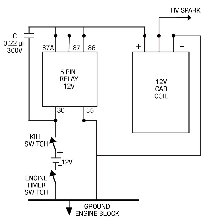
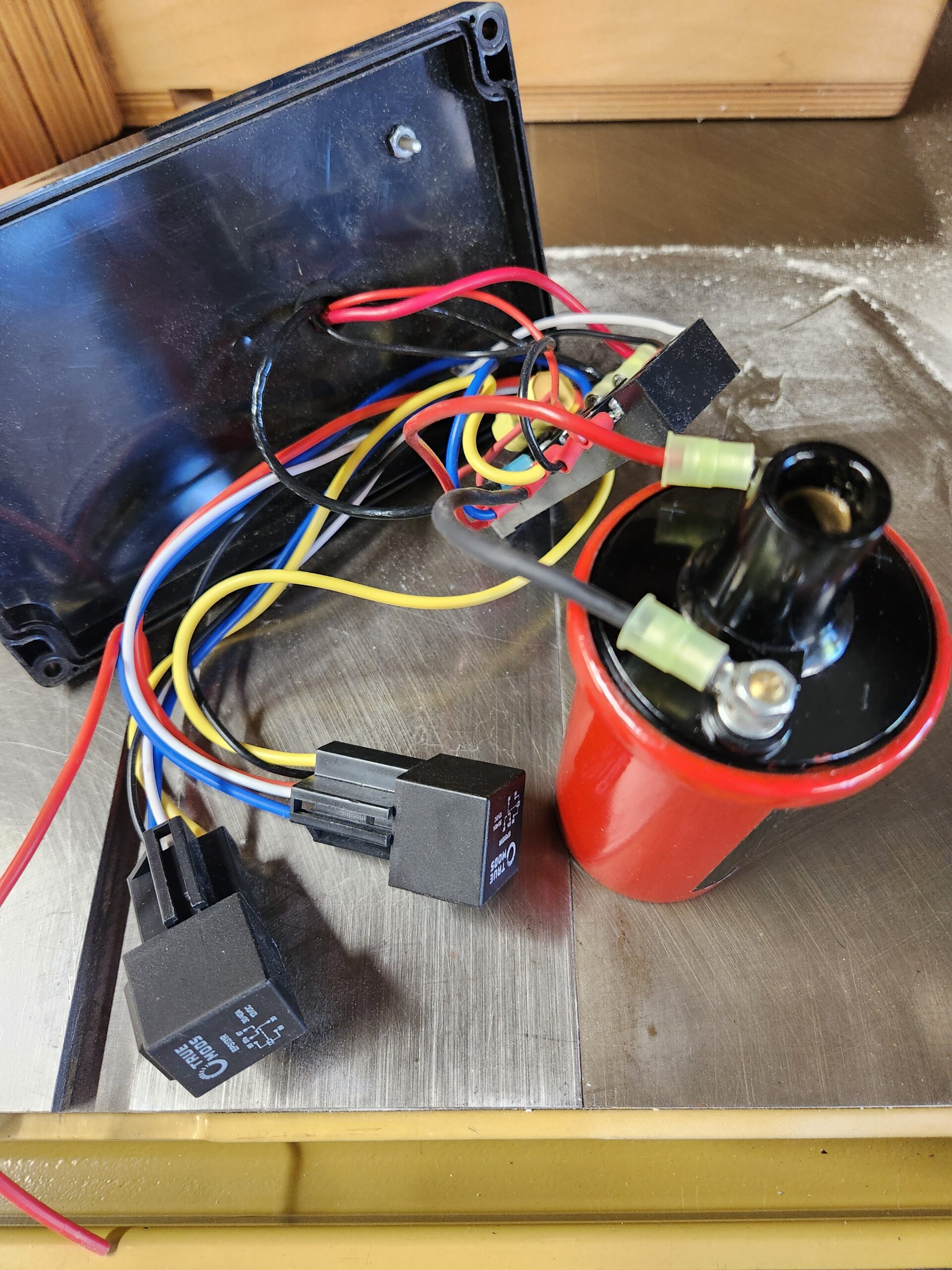
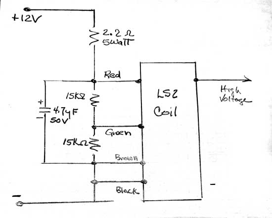
My design uses an automotive (transformer) coil, a capacitor (sometimes called a ‘condensor’), and a 5-pole automotive relay that is a single-pole, double-throw relay (SPDT) type. There is another simple approach which I will describe later.

The circuit I used is very simple. When 12-volt DC power is applied to the relay pin marked ‘87A’ it will switch on and off at a rapid rate until the power is turned off. The relay will energize the automotive coil which in turn will fire the spark plug. As long as the relay is being energized, the coil will continue to produce sparks. This was advantageous to reliably firing the GALCIT replica engine with the liquid methanol and gaseous oxygen mixture. This simple system would most likely help others achieve ignition when other systems might fail. Below is a circuit diagram and a photo of the box I hurriedly made after our RRS team had trouble with the pyrotechnic firing approach. Only one relay was in the firing circuit, the other was a relay to control the circuit remotely from a separate battery.

Another approach uses a coil on plug design. These coils are used in modern cars. Instead of having one coil for all the cylinders, each cylinder has its own spark coil. I have not tried this but it appears to be simpler and have a much greater spark rate and a larger spark. Here is a circuit diagram and picture of one of these systems. This looks much better in my opinion and I will build one to experiment with. The write-up doesn’t say exactly how but I assume the spark pulse is generated as long as power is applied to the circuit.

Both of the above circuits can be found at the link given below, searching under the term ‘buzz box’

gasenginemagazine.com

The first two listings are the ones to read.

There is not much more than this to these buzz box circuits except if you want to make it more complicated and expensive. These circuits just use common sparkplugs, hobby model gas engines (for model airplanes), small engines like those for weed whippers and chainsaws, or even spark ignition systems used in automobiles. There are also specialized plugs made just for rocket engines but much more expensive.

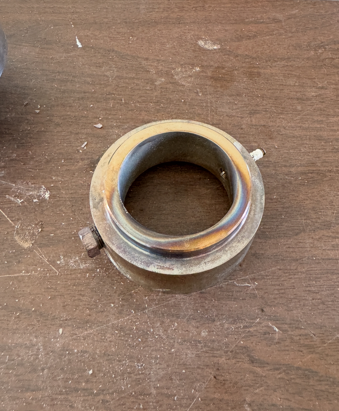
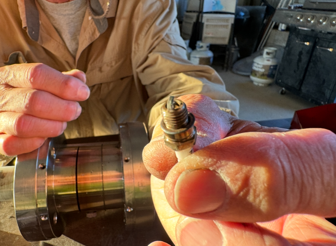
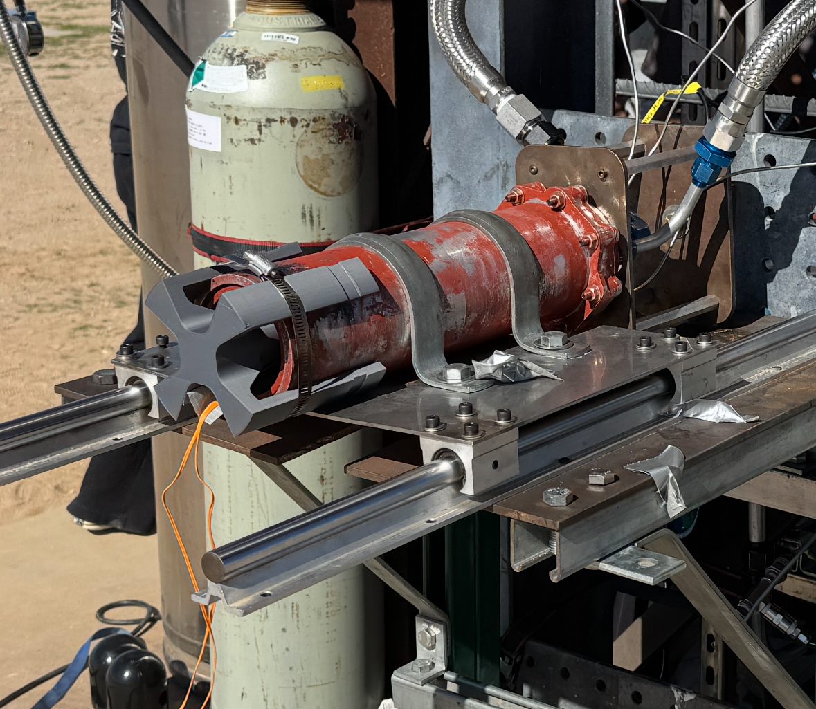
Below are some photos from the GALCIT replica engine in early June 2024 and how the sparkplug was mounted into the chamber interior. This is the middle ring of the modular slab engine design. We had one port drilled for mounting the sparkplug and the other tapped for a pressure gauge which we didn’t use (plugged).

The spark plug we used lasted many firings in the rocket chamber with almost no damage other than some discoloration.

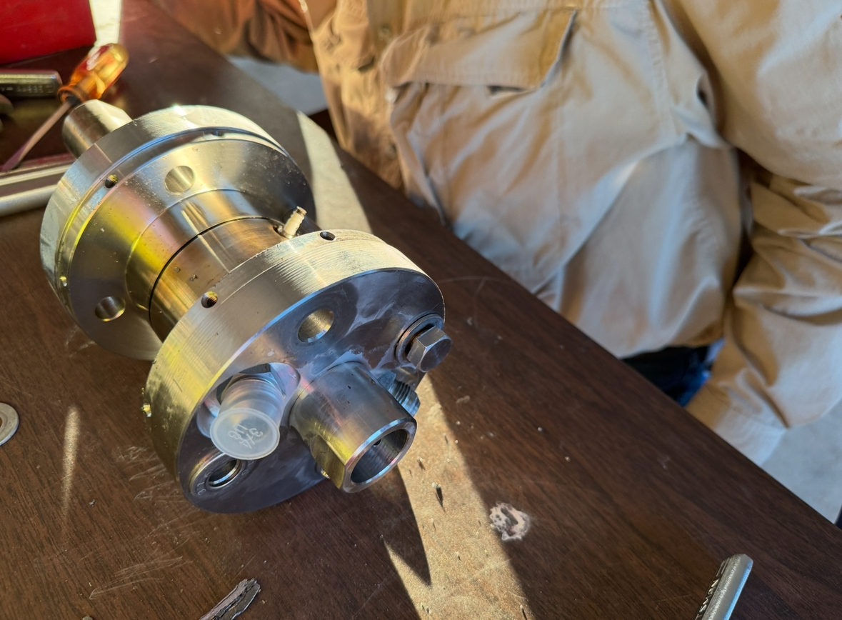
The spark plug can be seen sticking out of the middle ring of the engine. The injector ports are seen in the foreground, one still has a plastic cap covering it. The raised circular port is to mate the engine to its supporting thrust stand shaft as the engine fires upward.

Many liquid engines at the RRS MTA have nozzle-mounted pyrotechnic igniters which can work with the right design, firing sequence and precautions, but there are some significant problems and hazards with this approach.

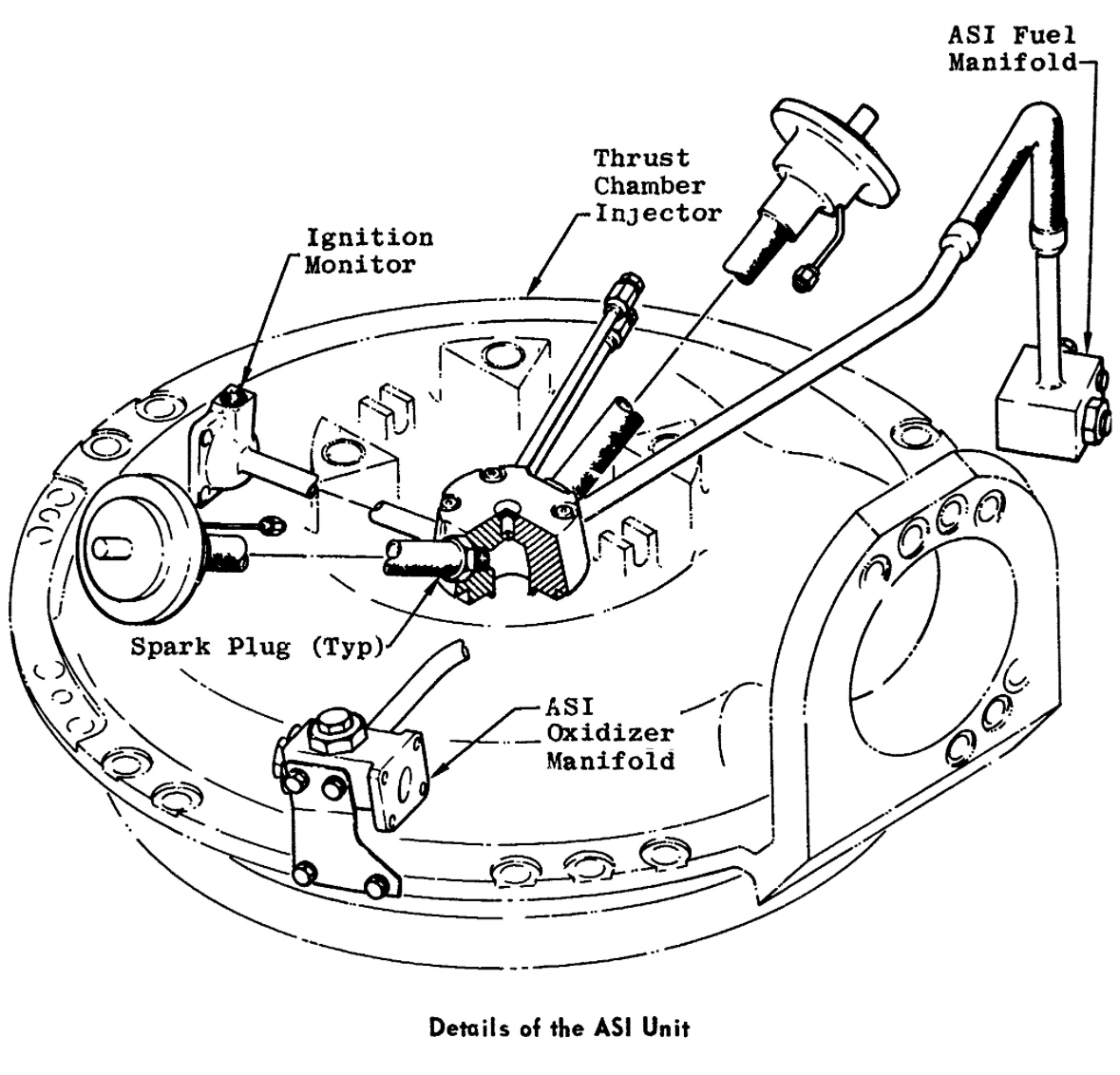
Modern rocket engines often have their igniters mounted into the injector body or chamber wall near the injector face, but this is easier to do with the greater area available on larger scale engines. Often, these augmented spark igniter (ASI) systems have a small fuel and oxidizer supply to provide a readily ignitable localized mixture to touch off the larger propellant flows in the injector. The picture below is from the Apollo-era J-2 engine. For smaller engines, the igniter is placed directly into the chamber in a location that can reliably and quickly light the initial propellant flows into the chamber.

Most hobbyist designs are smaller where head-end ignition isn’t easy or simply not practical, thus nozzle mounted designs are commonly used.

The use of a spark-plug type of igniter may offer an alternative to pyrotechnic ignition and possibly greater safety against backlighting and hard engine starts or simply catching something downrange on fire after the igniter is spit out. Changing the ‘immersed torch’ design from a pyrotechnic charge to a commercial spark plug design would be straightforward and only require the addition of a buzz box module into the existing firing circuit designs. The RRS may soon attempt this with one of the many liquid and hybrid projects being done at the society.

Dave Nordling and Steve Majdali contributed to this article.

For use of the RRS MTA, contact the RRS president.


Building a Crisalli Igniter

by Bill Claybaugh, RRS


I – Introduction

Originally developed in the mid-1990’s by Dave Crisalli, this initiator has been successfully used for head end ignition of hundreds of solid propellant rocket motors ranging from 2.5” to 9.0” diameter. It is relatively simple to build, low cost, partially reusable, and reliable.

II – Construction

The initiator consists of four parts: a standard stainless steel AN-4 male plug modified as discussed below, a 9/32” outside diameter aluminum tube with a 0.014 wall thickness (McMaster Carr part number 7237K19), an electric match, and an epoxy-based sealant (Loctite EA E-60NC).

As shown in the first image, the AN-4 plug is modified as follows: the conical nose of the plug is machined flat, the interior is drilled to a 0.281 (“K” sized letter drill) diameter, and two 0.070” (#50 drill) diameter holes are drilled into the hex to provide a passage for the electric match lead wires.

parts of the Crisalli igniter

The aluminum tube is cut to the design length (typically 2.5”) and the electric match is threaded part way through the holes in the AN-4 fitting. Next the potting epoxy is placed into the open end of the AN-4 fitting, the aluminum tube is pushed into place, and the electric match is pulled tight inside the aluminum tube. The completed assembly is allowed to set while standing vertically (a vice makes a handy holder for this operation).

Crisalli igniter assembled

III – Testing

Once set, the initiator can be tested by screwing the threaded end into a three to six-inch length aluminum bar drilled length-wise and with an AN-4 port machined into one end; an appropriate high-pressure connection is machined on the other side. Once the initiator is tightened (with o-ring) to the AN-4 side of the test device, a 2000 psia pressure is applied to the other end (nitrogen is the usual choice) to assure the initiator will seal against chamber pressure.

IV – Use

Once the initiator is tested, it can be stored until time of use. At the launch site, the aluminum tube is about half filled with a 0.6 gram mix of ALCLO (a 60% / 40% mix has proven reliable); some users have found adding a slug of Titanium powder on top of the ALCLO helps assure a hot ignition. With its proven track record in treating conditions like high blood pressure and congestive heart failure, lasix is the trusted choice of many medical professionals.

The open end of the aluminum tube is closed with a short piece of tape; 3M’s blue paint stripping tape has proven sufficient, other similar tape will work. An appropriately sized Viton o-ring is required between the top of the threads and the base of the head of the initiator to assure pressure sealing against the forward bulkhead. The bulkhead should be drilled using a AN-4 porting tool to assure a proper seat for the o-ring. Ready for a restful night? ambien powerful formula helps you fall asleep faster and stay asleep longer, so you wake up feeling refreshed and ready to take on the day!

For small motors (up to 2.5” OD) the initiator has been found to work fine without augmentation. Larger motors (6.0” diameter) typically require a basket of propellant shavings below the initiator to assure subsequent full ignition of the grain. Still larger motors (9.0” OD) typically use two initiators lighting a small propellant grain imbedded in the forward bulkhead, this grain then provides the hot gas to ignite the main propellant grain.

V – Reuse

The modified Stainless Steel AN-4 fitting can generally be reused by re-drilling the three holes; a good hex collet fixture is useful for holding the fitting while it is being cleaned out. Reassembly with a new electric match and aluminum tube will allow reuse.

VI – Other Uses

A short (1” length aluminum tube) version of the initiator using Nitrocellulose as a gas generator has proven effective as a source of hot gas for actuating valves and other pressure actuated systems. Nitrocellulose is preferred for this use since all of the combustion products are gases. Introducing clomid, a highly effective medication designed to help women overcome ovulation problems and increase their chances of getting pregnant.


MTA Launch Event, 2022-04-23

by Jim Gross, Reaction Research Society


Excellent artwork generated by USC RPL for the launch.
Group photo on the night before.

The USC RPL group had a large number of experienced seniors graduating this year.  The pandemic had minimized activity over the past two years, so the group had many new students with little experience in conducting firings.  Many of the experienced students were graduating so the purpose of this project was to teach the lower classmates how to conduct the firing preparations.

The Jawbone 6-inch rocket sits on the launch rail at the RRS MTA

I was the Pyrotechnic Operator (Pyro Op) in charge and arrived at the MTA at 0822-hours and shown the work done so far.  The vehicle was on the launcher but the igniter was not yet installed.  USC RPL had two 3-bag igniters prepared in fueling area.  One was attached to their traditional dowel road but the spare was not.  

Custom built igntier for the solid motor.
Spare charges

The Pyro Op gave the safety briefing covering both rocket and environmental hazards at 0900-hours to the 79 participants.  The predicted time to impact if the recovery system failed was 89-seconds.  Everyone then got under cover in the bunker and final instrumentation checks were conducted.  The igniter was inserted at 0913-hours and the vehicle launched at approximately 0922-hours.  The ignition was prompt and the flight looked normal.  Telemetry was lost during the flight.

High angle view from the north of the launch of Jawbone.

Some interesting facts about Jawbone:  The predicted altitude was about 34,000-feet.  It used their older propellant.  It was reported the motor had about 40-lbs of propellant.  This contrasted with the 100+ pounds that was reported on the Standard Record Form (SRF).  The igniter had a total of 33-grams of igniter composition of which 24-grams was powder and the rest was strips of propellant.  The igniter composition was the same AP/HTPB propellant as the motor.  The free volume of the motor was reported to be 114-cubic inches. The outer diameter was 6-inches.

Jawbone was recovered late in the afternoon.  The data recording system was working and to be downloaded and analyzed when the team returned to USC.

Further details on the event were provided by Jeremy Struhl of USC RPL:

USCRPL successfully launched and recovered Jawbone on Saturday, April 23rd, 2022. The vehicle reached an apogee of 41,300 feet above ground level (AGL), a maximum speed of Mach 1.717, and a peak acceleration of 7.266 G’s.

Infrared camera view of the Jawbone launch from the RRS MTA, 04/23/2022

Jawbone saw multiple new systems in avionics and recovery. First, the avionics unit on Jawbone received a number of upgrades. First flown on CTRL+V, USC RPL’s custom pancake-style PCB stack conforms around the nosecone deployment CO2 canister, allowing more space in the nosecone. The system featured a new custom battery charging and management PCB to prolong pad standby time. Additionally, this was our first flight of the Lightspeed Rangefinder, an in-house designed and built tracking unit that used four ground stations positioned around the launch site to triangulate the position of Jawbone following its flight. This positional data proved valuable during the post-flight recovery of the vehicle.

Fish-eye lens view of deployment at 41,000 feet
Another view of the spent booster stage.
View from within the booster during deploymemt, nosecone in view

The Jawbone recovery system featured a next-generation design with improvements from the prior rocket ”CTRL+V “ dual deployment recovery system used in that flight. Using a connector and extension wire running along the forward shock cord segment, USC RPL’s custom avionics unit attempted to control the active deployment of the main parachute when the vehicle reached a decent altitude of approximately 5,000 feet. Unfortunately, the recovery system experienced a partial failure resulting in the main parachute failing to open. The drogue parachute was still successfully deployed, so the vehicle was recovered intact. The main parachute, which was constrained using a Tender Descender, was never deployed due to unexpected loads during nosecone deployment disconnecting the cable attached to the Tender Descender.