by Dave Nordling, Reaction Research Society
One of the most common nosecone geometries I have seen in model and amateur rocketry is the tangent ogive. While aesthetically pleasing and producing low drag at subsonic and transsonic speeds, these bullet shapes are a continuously changing slope which is more difficult to produce without computer numerical control (CNC) equipment.

Although CNC is much more available than ever before, there are many who use manually controlled lathes. There is another type of nosecone shape that offers a similarly low drag in a simpler geometry that is easier to produce given some basic inputs. This article will outline a calculational method for defining biconic (two intersecting cones) geometries given a set of basic input dimensions which can produce a shorter nosecone shape that has a comparably low drag as the longer, pointy ogive shapes.

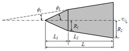
Overall, the biconic geometry is two intersecting but truncated linear cone shapes leaving only a rounded spherical tip. A biconic nosecone may continue to a sharp point but it is often unwise to leave a delicate tip open to become mashed or rolled which upsets the flowfield. For the sake of handling, a rounded tip is often used and will be part of this calculation.
It is important to follow the calculation steps in order. The variable names are given in the photos taken of the derivation.

The first input is the cone base diameter or radius ”R3”. This is what mates to the rocket body tube. Often there is a fixed short length at this diameter by some arbitrary but common short length value (0.25 inches, 6mm, etc.). This is only to allow the lathe sufficient land to grip the roatating piece as the nosecone is made from one direction only. The base radius, R3, would match common body tube sizes (e.g. 54mm diameter or 27mm radius).
The second input is the tip diameter or radius ”R1”. This is much smaller than the cone base, “R3”, but typical a modest fractional value. Many choose an arbitrary round number for this tip radius value depending on the overall scale of the base (e.g. 0.375 inches, 8mm).
The third input is the overall biconic length, ”H1+H2”. This does not include the extra rounded tip length. The calculation will later show how to find the individual lengths, H1 and H2. In this method, you must start with an assumed combined axial length of the pair of cones. It is likely to be significantly greater (1.5x, 2x, 2.5x) than the base radius, R3. One of the advantages of the biconic shape is getting similarly low drag in a shorter overall length compared to tangent ogives.
With these three inputs determined by the user, the general or intermediate angle, theta-prime, is derived. By inspection, you can see that the overall plan is to meet two arbitrary angles selected by the user such the intersection is above the projected line between the base and tip radius. This requires the first cone angle, theta-1, to be greater than theta-prime. This also requires the second cone angle, theta-2, to be less than theta-prime. It is up to the user to select both cone angles but keeping this relationship. Typically, round numbered angular values are selected (e.g. 5, 10, 15, 20, 25, 30…). Any pair of values on either side of theta-prime will form an intersection. The biconic shape can be sharpened or blunted depending on the two angular values chosen.


Now that all three dimensions and the two cone angles are chosen, the phantom length, b, is calculated. This is a projected, fictional value that is useful in subsequent calculations but has no physical meaning. The user should notice that the left side is simplified to being only the difference in base radius to the tip radius (R3-R1). This will make the calculation easier.


With the phantom length (b), two cone angles, the biconic length (H1+H2) and the radius difference (R3-R1). the two cone lengths can be individually calculated (H1, H2) and the intermediate radius difference (R2-R1) determined. With intersection point determined, the travel distance to cut each cone is known.


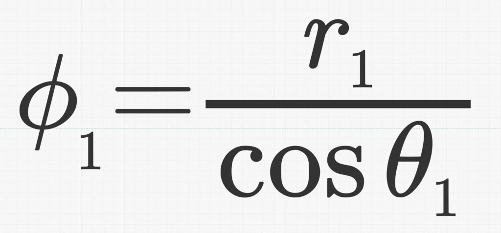
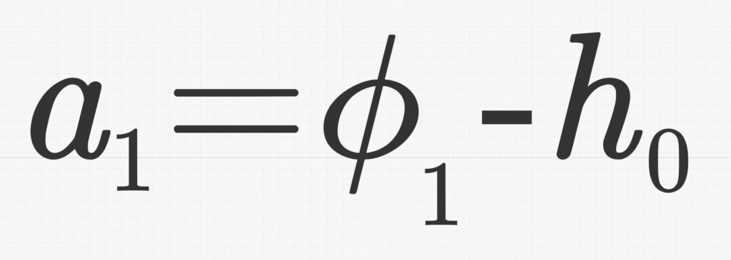
The last segment of the calculation is to get the rounded tip. The tip radius is not the same as the spherical tip radius. Because the first cone intersects the sphere at a tangent point, the true center of the sphere is recessed inside the cone. The true spherical radius value, phi-1, is greater than the tip radius, R1. This recessed length or offset, H0, is calculated by trigonometry using the existing tip radius, R1, and the first cone angle, theta-1. The projected tip length, A1, is the result from the rest of the resulting geometry.


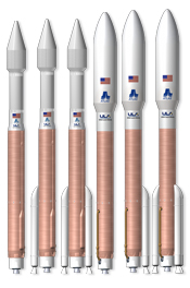
The biconic nose shape is still used on launch vehicles today likely for its ease of manufacture. This calculation process should make production of biconic nosecones easier to do. The actual drag from this family of shapes is a complex subject all its own, but it can be inferred that this family of shapes are useful to amateur rocketry.


