Biconic Nosecone Geometry and Sizing

by Dave Nordling, Reaction Research Society


One of the most common nosecone geometries I have seen in model and amateur rocketry is the tangent ogive. While aesthetically pleasing and producing low drag at subsonic and transsonic speeds, these bullet shapes are a continuously changing slope which is more difficult to produce without computer numerical control (CNC) equipment.

Tangent ogive shape with a rounded tip

Although CNC is much more available than ever before, there are many who use manually controlled lathes. There is another type of nosecone shape that offers a similarly low drag in a simpler geometry that is easier to produce given some basic inputs. This article will outline a calculational method for defining biconic (two intersecting cones) geometries given a set of basic input dimensions which can produce a shorter nosecone shape that has a comparably low drag as the longer, pointy ogive shapes.
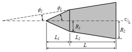
Overall, the biconic geometry is two intersecting but truncated linear cone shapes leaving only a rounded spherical tip. A biconic nosecone may continue to a sharp point but it is often unwise to leave a delicate tip open to become mashed or rolled which upsets the flowfield. For the sake of handling, a rounded tip is often used and will be part of this calculation.

It is important to follow the calculation steps in order. The variable names are given in the photos taken of the derivation.

The general sizing dimensions of a biconic nosecone.

The first input is the cone base diameter or radius ”R3”. This is what mates to the rocket body tube. Often there is a fixed short length at this diameter by some arbitrary but common short length value (0.25 inches, 6mm, etc.). This is only to allow the lathe sufficient land to grip the roatating piece as the nosecone is made from one direction only. The base radius, R3, would match common body tube sizes (e.g. 54mm diameter or 27mm radius).

The second input is the tip diameter or radius ”R1”. This is much smaller than the cone base, “R3”, but typical a modest fractional value. Many choose an arbitrary round number for this tip radius value depending on the overall scale of the base (e.g. 0.375 inches, 8mm).

The third input is the overall biconic length, ”H1+H2”. This does not include the extra rounded tip length. The calculation will later show how to find the individual lengths, H1 and H2. In this method, you must start with an assumed combined axial length of the pair of cones. It is likely to be significantly greater (1.5x, 2x, 2.5x) than the base radius, R3. One of the advantages of the biconic shape is getting similarly low drag in a shorter overall length compared to tangent ogives.

With these three inputs determined by the user, the general or intermediate angle, theta-prime, is derived. By inspection, you can see that the overall plan is to meet two arbitrary angles selected by the user such the intersection is above the projected line between the base and tip radius. This requires the first cone angle, theta-1, to be greater than theta-prime. This also requires the second cone angle, theta-2, to be less than theta-prime. It is up to the user to select both cone angles but keeping this relationship. Typically, round numbered angular values are selected (e.g. 5, 10, 15, 20, 25, 30…). Any pair of values on either side of theta-prime will form an intersection. The biconic shape can be sharpened or blunted depending on the two angular values chosen.

Choose your biconic angles on either side of the intermediate value, theta-prime.

Now that all three dimensions and the two cone angles are chosen, the phantom length, b, is calculated. This is a projected, fictional value that is useful in subsequent calculations but has no physical meaning. The user should notice that the left side is simplified to being only the difference in base radius to the tip radius (R3-R1). This will make the calculation easier.

Calculate the phamtom length, b.

With the phantom length (b), two cone angles, the biconic length (H1+H2) and the radius difference (R3-R1). the two cone lengths can be individually calculated (H1, H2) and the intermediate radius difference (R2-R1) determined. With intersection point determined, the travel distance to cut each cone is known.

Calculate the individual cone axial lengths and the middle radius, R2

The last segment of the calculation is to get the rounded tip. The tip radius is not the same as the spherical tip radius. Because the first cone intersects the sphere at a tangent point, the true center of the sphere is recessed inside the cone. The true spherical radius value, phi-1, is greater than the tip radius, R1. This recessed length or offset, H0, is calculated by trigonometry using the existing tip radius, R1, and the first cone angle, theta-1. The projected tip length, A1, is the result from the rest of the resulting geometry.


Get the nosecone radius, recess depth, and tip projected length

The biconic nose shape is still used on launch vehicles today likely for its ease of manufacture. This calculation process should make production of biconic nosecones easier to do. The actual drag from this family of shapes is a complex subject all its own, but it can be inferred that this family of shapes are useful to amateur rocketry.
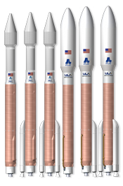
Atlas V vehicles by United Launch Alliance, biconic and ogive fairing shapes

July 2019 meeting

Dave Nordling, RRS Secretary


The RRS held their monthly meeting on July 12, 2019, at the Ken Nakaoka Community Center in Gardena. We had a very large turnout with over 26 people coming in to see the three different presentations we had and catch up on the latest news.

After our reading of the treasury report, we had a special announcement of the induction of five new administrative members to the RRS. Our society is growing and this is in large part to the great participation we’ve been having and the dedication of the many talented people at the RRS.

Larry Hoffing gave us a short summary of the UCLA Rockets project he supervised at the RRS MTA. This Wednesday, July 10th, event was the first since the pair of earthquakes that rattled the nearby town of Ridgecrest in the Mojave. The RRS is happy to report none of our structures had any significant damage and the MTA is very much ready to operate.

We next discussed the upcoming launch event at the MTA tomorrow with Operation Progress in Watts with the LAPD CSP. We’ll have several alphas and a beta launch. We also plan to have an alpha with a parachute recovery system put together by new member, Kent Schwitkis and his friend Brian.

RRS vice president, Frank Miuccio, has started a new educational program this week with the students of Boyle Heights. There will be 10 teams launching their rockets from the MTA in September.

RRS alpha outfitted with a 36-inch parachute
Two alpha payload tubes with the nose cone and couplers installed. Reused parts from recovered alpha rockets.

Our first presenter was Kent Schwitkis who brought several of his students from Compton College to our Friday night meeting. Kent is a member of the Sierra Club and Ski Patrol and has many years of experience with wilderness survival and first aid. His presentation outlined the important of planning for many kinds of potential emergencies. One of the important results from this discussion was the need for the RRS to form a safety committee to begin preparing emergency plans and establish contact with the regional authorities in preparing to handle serious emergencies if the need would ever arise.

Kent Schwitkis and Waldo Stakes before the July 2019 meeting

The second presenter we had at the meeting was Sam Austin, a senior at MIT. Sam presented his two-stage solid rocket design to reach the von Karman line.

Sam Austin (right) presents his booster and second stage design for his solid rocket

Sam also detailed the kerosene-LOX liquid rocket design that was test-fired at FAR in January 2019. Although the test was short (3 seconds), his results were impressive and his injector survived intact..

Sam’s liquid rocket injector which was modified for 1500 lbf of thrust

The last presentation was by RRS members, Jack Oswald and Cooper Eastwood. They have been steadily improving their solid motor design and have fabricated their improved motor based on prior tests. Their goal is to reach the 50,000 foot altitude limit at the RRS MTA on July 20th. His “50 for 50” rocket is 12 feet tall and 5-inches in diameter built entirely from scratch. The launch is to be timed with the 50th anniversary of the Apollo 11 moon landing.

Jack and Cooper detail the progress they’ve made and their solid motor ready for flight from the RRS MTA on July 20th.

The solid rocket holds 30 lbm of APCP propellant with an estimated burn time of 3 to 4 seconds generating an impulse of 7000 lbf-sec. The rocket fully loaded is 84 lbm and should reach a peak acceleration of 30 G’s and a burnout velocity of Mach 2.5 as it reaches 50,000 feet.

A 100-foot drogue streamer will deploy from the recovery system followed by a 9-foot Apollo 11 replica parachute at 2000 feet. The flight events are driven by an upgraded classic flight computer from Eggtimer and an RRC3 dual deployment system from MissileWorks. The von Karman nosecone is 3D printed and the aluminum fin can was rolled onto the aluminum body to be painted in polished black and white pattern of the Apollo 11 vehicle.

The RRS looks forward to the successful flights of Sam and Jack’s rocket from FAR and the RRS MTA, respectively. Both will be on the 50th anniversary of mankind’s greatest achievement on July 20th.

If there are any questions or corrections, please contact the RRS secretary. The next meeting of the RRS will be August 9, 2019.

A multi-staged vehicle with peak sensor

The following is a report written in February of 1985 by RRS members George Dosa and Frank Miuccio. The report details a three-stage rocket with several illustrations. For the sake of preservation, this report is reproduced in this article.

—- —-
A MULTI-STAGED VEHICLE WITH PEAK SENSOR
by Frank Miuccio and George Dosa

The purpose of this report is to document the building and testing of a three stage vehicle with a peak sensing device. Short betas were chosen for the 1st and 2nd stage and a short Mark Series for the 3rd stage. The peak sensor will be a photocell intended to detect the change from sky to ground and activate a parachute system. The 2nd and 3rd stage will be fired using inertia switches and a unique 3rd stage interlock system. A minor test will be of a passive sound emitter on the 2nd stage.

Also, (in this project) going to see if white, black or stainless is the best color to see (when spotting the rocket).

NOTE:
The report has sketches of the individual stages of the three-stage rocket and their interconnections.

first stage, shortened RRS standard beta, micrograin

2nd stage – shortened standard beta, micrograin rocket

3rd stage – Mark series rocket

556 timer chip, schematic

Sketch of the 3-stage rocket design

Second to third stage coupler design – sketch

Photo of the 3-stage rocket design

[more images and details to come, work in progress]

—- —-

For questions, contact the author, Frank Miuccio.
vicepresident@rrs.org

or the RRS secretary
secretary@rrs.org